Using the Embedded IP Address as the Static IP Address
Although Keyscan does not recommend this, as an option the embedded programming IP
address may also be used as the static IP address. If you elect to do this you only need to
set the embedded IP address as outlined in the instructions below. The device does not
have to be programmed with the Keyscan NETCOM Program Utility. In the Client software,
the panels on the communication loop must have the embedded programming IP specified.
Using the embedded programming IP address restricts your communication with the panels
to a local network connection and you can only use a NETCOM2 Rev. B once per embedded
IP.
NETCOM2 Rev. B Bit Rate Setting
DIP switches S2.2 & S2.3 regulate the NETCOM2 Rev. B’s bit rate setting. The NETCOM2
Rev. B’s bit rate setting must match the bit rate setting of the control boards on the
communication loop. The bit rate on the control board is determined by J16 jumpers or S2
DIP switches. The bit rate is the number of bits processed per second at one of the speeds
listed in the table.
Table 3 – DIP Switch Bit Rate Settings
Steps to Install and Configure the NETCOM2 Rev. B
Ensure that you know which embedded programming IP address to select based on the IP
addresses used on the network and you know the control board bit rate setting. Space is
provided at the back for recording the IP address, Subnet Mask, Gateway and MAC
address.
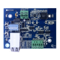
1. Mount and connect the NETCOM2 Rev. B as shown in either Figure 3 or Figure 4
within the ACU metal enclosure.
2. Ensure the S2.1 DIP switch is in the off position.
3. Connect the NETCOM2 Rev. B to the power. Observe that the POWER LED illuminates.
4. Set the S2.4 and S2.5 DIP switches to the correct embedded programming IP address
in accordance with the network. Refer to Table 2.
5. Set the S2.2 and S2.3 DIP switches to the same bit rate setting as the control boards.
Refer to Table 3. If connecting with DSC, match NETCOM to DSC bit rate setting.
6. Set the S2.1 DIP switch to the ON position.
7. Press and release the S3 PROGRAM button. Observe the PROGRAM LED illuminates –
solid – and the RD LED - flashes.
8. Press and release the S1 RESET button. Observe the following LED sequences:
After flashing for approximately 2 seconds the TD, RD and PROGRAM LEDs turn
off.
9. Change the S2.1 DIP switch to the off position.
Continued on the next page…