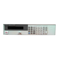
The Keysight Models 66312A, 66332A Dynamic Measurement DC Sources, and Keysight Models 6631B, 6632B, 6633B, 6634B, 6611C, 6612C, 6613C, and 6614C System DC Power Supplies are GPIB programmable DC power supplies designed for remote programming and various measurement applications.
Function Description:
These devices serve as programmable DC power sources, offering control over output voltage and current. A key feature, especially for the 66312A and 66332A models, is their dynamic measurement capability, making them particularly useful for loads that draw current in pulses. The power supplies can be programmed to turn off their output if the output voltage or current exceeds a preset limit, providing protection features.
The devices incorporate two independent trigger systems: one for generating output changes (transient trigger system, SEQuence1) and another for triggering measurements (measurement trigger system, SEQuence2 or ACQuire). This allows for synchronized data acquisition with output voltage or current transitions.
Important Technical Specifications:
- GPIB Interface: All DC source functions, except for setting the GPIB address, are programmable over the GPIB. The devices conform to IEEE 488.2 standards.
- RS-232 Interface: An RS-232 programming interface is available, activated via the front panel Address key. All SCPI and COMPatibility commands are accessible through RS-232. When RS-232 is active, the GPIB interface is disabled.
- Data Format: 10-bit word with one start bit and one stop bit (fixed).
- Parity Options: Selectable via front panel (EVEN, ODD, MARK, SPACE, NONE), stored in non-volatile memory.
- Baud Rates: Selectable (300, 600, 1200, 2400, 4800, 9600), stored in non-volatile memory.
- Flow Control: Supports XON-XOFF, RTS-CTS, DTR-DSR, and NONE.
- Output Voltage and Current: Programmable output voltage and current limits. Maximum RMS output voltage and current can be queried.
- Current Measurement Ranges: Two ranges (MIN and MAX). The MIN range measures up to 20 milliamperes, while the MAX range covers the full current measurement capability.
- Measurement Sampling Rate: Output voltage or current sampling rate is 15.6 microseconds at *RST, resulting in a 32-millisecond data acquisition time for 2048 data points. This rate can be varied.
- Data Buffer: Measurements are performed by digitizing instantaneous output voltage or current, storing results in a buffer. The total number of data points cannot exceed 4096 (trigger count multiplied by sweep points).
- Measurement Window Functions: HANNing (for reducing errors in DC and RMS measurements with periodic signals) and RECTangular (for measurements without signal conditioning, useful when the pulse waveform period is known).
- Status Registers: Includes Operation Status, Questionable Status, Standard Event Status, and Status Byte registers, conforming to IEEE 488.2. These registers allow monitoring of operating conditions and generating service requests (SRQ) for events like current limits or overvoltage protection trips.
- Power-On Conditions: At power-on, the output state is OFF, output voltage is 0, and status registers are implicitly reset.
- Non-Volatile Memory: Stores GPIB address, RS-232 parity options, baud rates, calibration passwords, power-on states, and saved instrument states. Repeated write cycles to non-volatile memory (e.g., via *PSC or *SAV commands) can eventually cause memory failure.
Usage Features:
- Remote Programming: Primarily designed for remote control via GPIB or RS-232 using SCPI (Standard Commands for Programmable Instruments) commands. Compatibility language mode is also available for emulation of older DC source systems.
- Instrument Drivers: VXIplug&play instrument drivers for Microsoft Windows 95 and Windows NT are available, providing a high-level programming interface for various application environments (Keysight VEE, Microsoft Visual BASIC, C/C++, Borland C/C++, National Instruments LabVIEW, LabWindows/CVI).
- Output Control: Commands to enable/disable output, set voltage and current levels, and configure overcurrent and overvoltage protection.
- Triggering:
- Output Trigger System (SEQuence1/TRANsient): Used for generating output changes. Can be initiated for single or continuous triggered actions. Trigger sources are limited to the GPIB bus.
- Measurement Trigger System (SEQuence2/ACQuire): Used for synchronizing data acquisition. Trigger sources can be GPIB bus or internal (output signal crossing a specified level with a defined slope and hysteresis).
- Measurements:
- MEASure commands: Immediately acquire new data and return calculations.
- FETCh commands: Return calculations from previously acquired data (useful for triggered measurements).
- RMS Measurements (66312A, 66332A Only): Measure total RMS content of voltage or current waveforms.
- Minimum and Maximum Measurements (66312A, 66332A Only): Measure peak minimum or maximum voltage/current of pulses or AC waveforms.
- Array Measurements (66312A, 66332A Only): Return all instantaneous voltage or current data values from the buffer.
- Pre-event and Post-event Triggering (66312A, 66332A Only): Allows offsetting the acquisition buffer relative to the trigger to capture data before or after an event.
- Status Monitoring: Program status registers to detect operating conditions (e.g., constant current mode, overvoltage trip) and generate service requests (SRQ) for interrupt-driven error handling.
- Display Control: Commands to turn the front panel display on/off, set display mode (NORM/TEXT), and send custom text messages to the display.
- Device Clear: Allows aborting SCPI commands and clearing input/output buffers. For RS-232, sending a Break performs this function.
Maintenance Features:
- Calibration: Commands to enable/disable calibration mode, change calibration passwords, and calibrate current and voltage programming and measurement circuits. New calibration constants can be saved to non-volatile memory.
- *Self-Test (TST?): Initiates a self-test and reports errors, which are also written to the error queue.
- Error Handling: Provides error numbers and descriptions for SCPI syntax errors, interface problems, and device-dependent errors, accessible via the SYSTem:ERRor? query or front panel.
- Inhibit/Fault Indicator: Remote Inhibit (INH) and Discrete Fault Indicator (DFI) connections on the rear panel allow external devices to signal faults or be signaled by fault conditions. The DFI port can also be configured as a general-purpose digital I/O port.
- *Power-on State Configuration (PSC): Controls automatic clearing of Service Request Enable and Standard Event Status Enable registers at power-on, or saves/recalls their contents from non-volatile memory.