124 Keysight FieldFox Handheld Analyzers Service Guide
Repair and Replacement Procedures
Removing and Replacing the Case Group Parts
7-
9. Reinstall the measurement group assemblies (RF top panel assembly, A4
RF board, A5 System board, and A6 SOM board) as one unit with the new
I/O panel attached.
10.Reinstall the rear case onto the front case. See Combining the Front and
Rear Cases.
Replacing the Front Case (including the A1 Keypad)
1. Separate the front and rear cases. See Separating the Front and Rear
Cases.
2. Remove the measurement group assemblies (RF top panel assembly, A4
RF board, A5 System board, and A6 SOM board) as one unit with the I/O
panel attached. Refer to “Removing and Replacing the Measurement
Group Assemblies” on page 136.
3. Remove the front panel group assemblies (A2 LCD, A3 front panel
interface board, and RPG). Refer to “Removing and Replacing the Front
Panel Group Assemblies” on page 130.
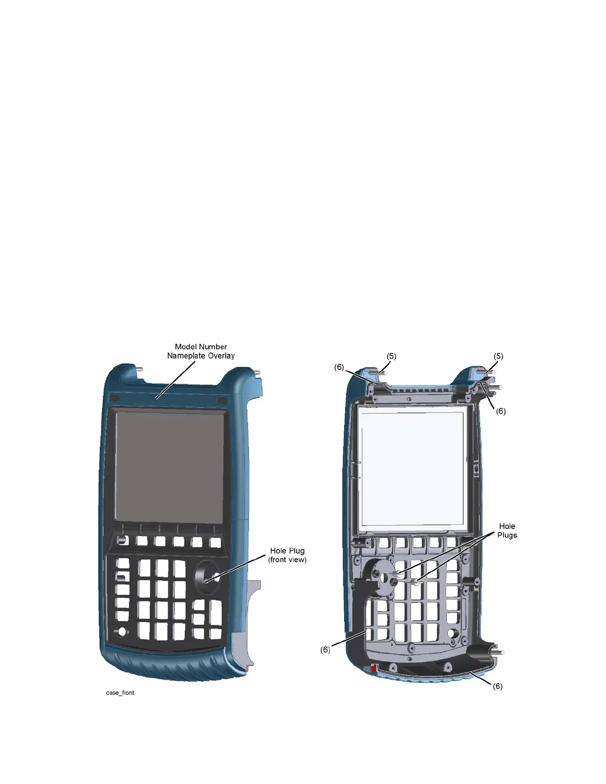
Figure 7-13 Replacing the Front Case
 Loading...


