50 Keysight FieldFox Handheld Analyzers Service Guide
Troubleshooting
Measurement Group Troubleshooting
4-
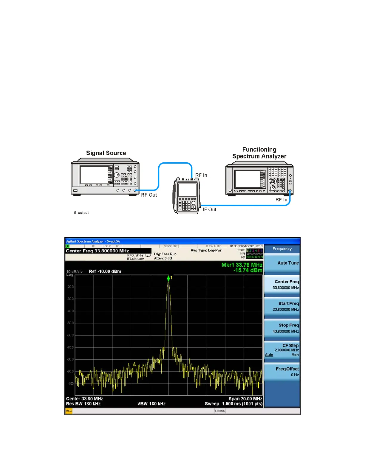
Inject that 1 GHz CW signal into the Port 2 SA RF Input connector on the
instrument as illustrated in Figure 4-4 From an instrument preset, tune the
instrument to 1 GHz, 0 Span. Verify that the input attenuator (Atten) is set to
10 dB. On the side of the instrument near the RPG tuning knob, there is a
spring door. Open that spring door and locate the IF Out SMB (m) connector.
Connect one end of a test cable to the IF Out connector on the side of the
instrument. Connect the other end of the test cable to the functioning
spectrum analyzer. Tune the functioning spectrum analyzer to 33.75 MHz. The
I.F. Out signal level should measure 33.75 MHz at approximately -16 dBm as
illustrated in Figure 4-5
Figure 4-4 33.75 MHz I.F. Output Test Setup
Figure 4-5 33.75 MHz I.F. Output Signal
 Loading...


