Keysight PXI/AXIe Chassis Reference Guide 11
Understand the system hardware connections
AXIe Chassis Backplane and Module Layouts
Keysight AXIe chassis are fully compatible with the AXIe 1.0 specification. Figures
7, 8, and 9 below show the chassis backplane, with modules removed from all
slots.
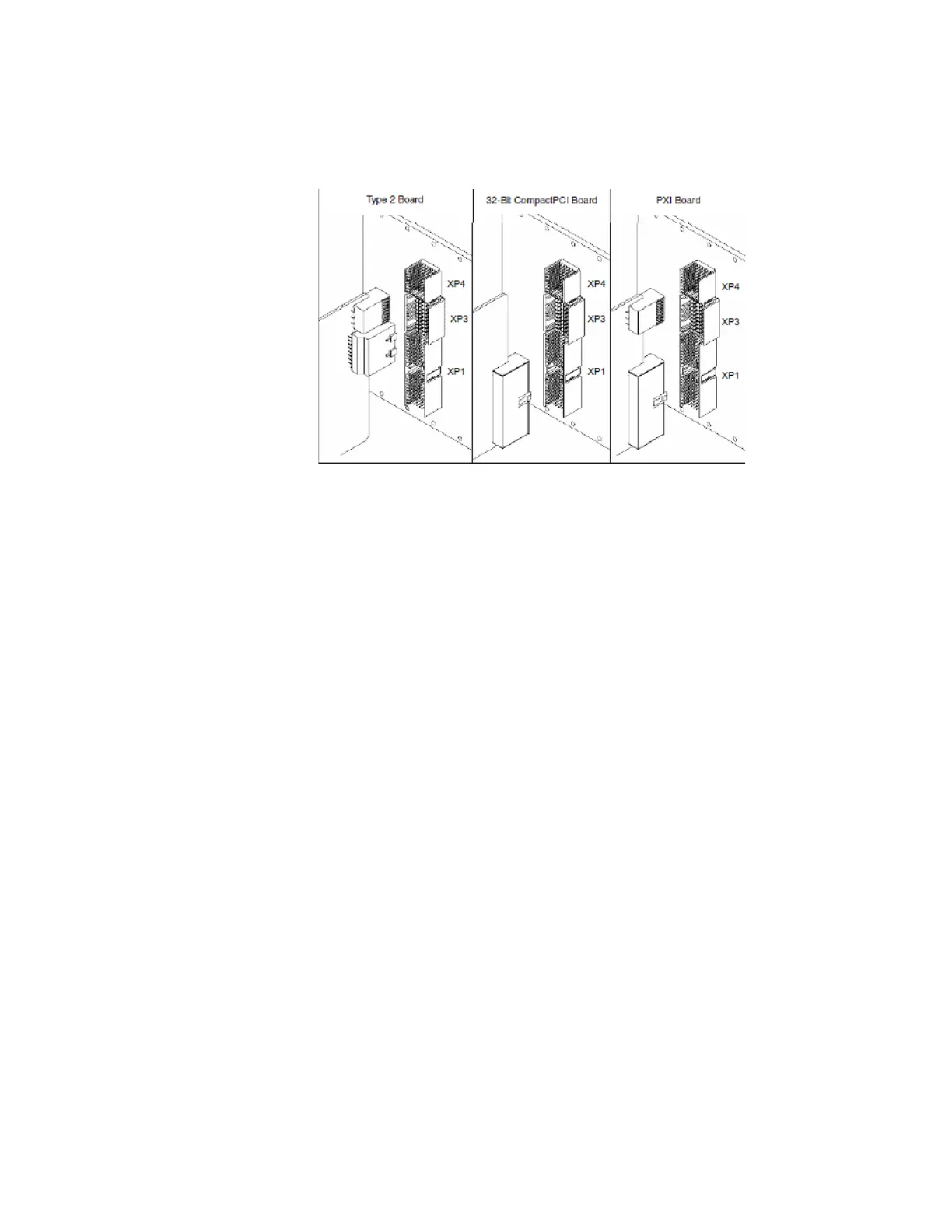
The backplane provides Zone 1 connector J10 and Zone 2 connectors P20, P21,
P22, P23, P24. Connector designations are shown for instrument slot 1. The
M9502A backplane differs from the M9505A and M9506A in that the 2-slot
backplane does not use P22. A typical module layout is shown below the
backplane photos, with the mating connectors J20 through J24 and P10.
Depending on module type, the module may implement all or none of J20-J24.
Connector P10 is required to power the module. Refer to the AXIe chassis' user
guide for pin-out details.
Figure 6 PXIe Hybrid Slots Detail