17
Getting Started
STEP 4. Install the Network Analyzer Modules
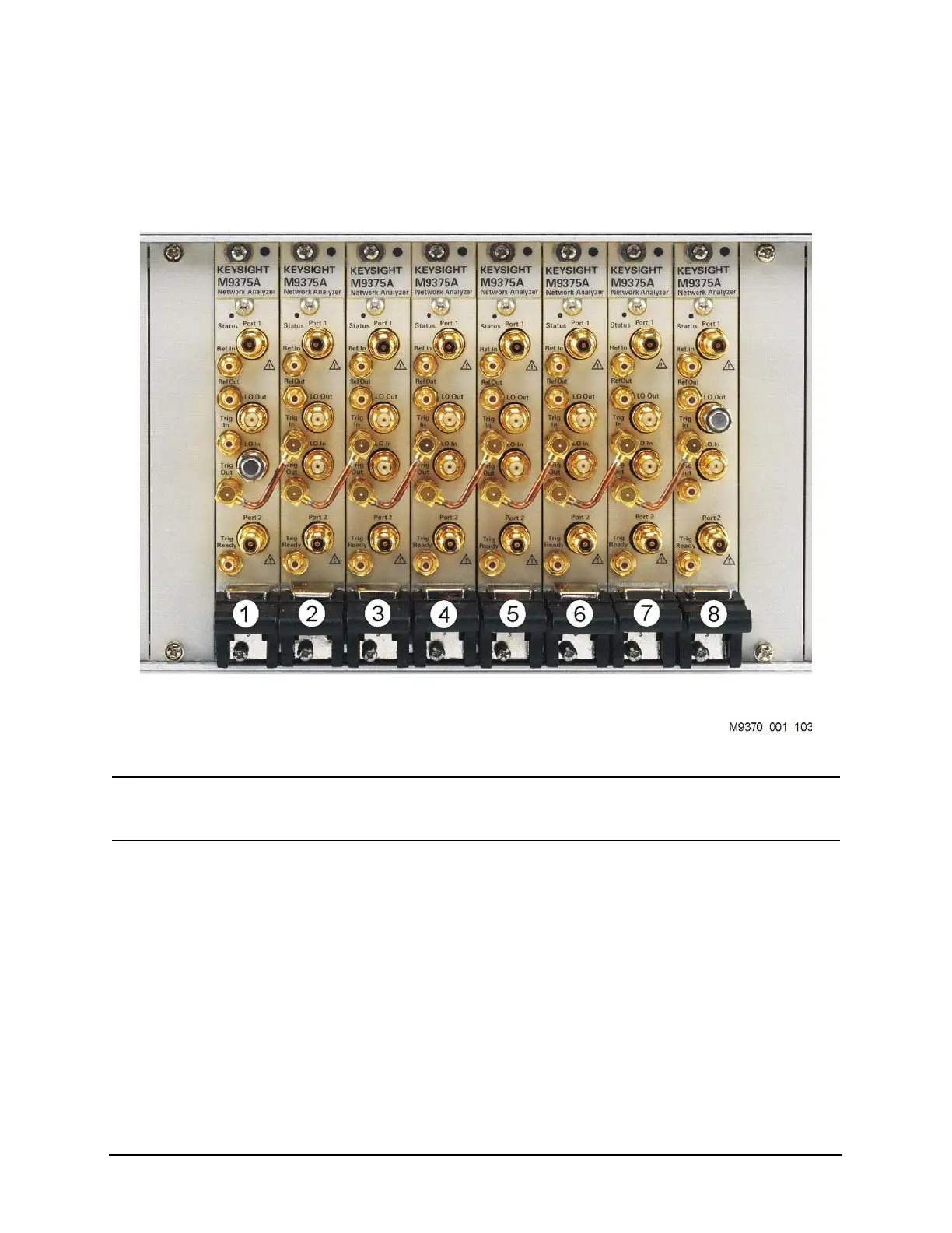
12.Install a semi-rigid cable (M9370-20018), seen in Figure 1-7, between the
Trig Out port and the Trig In port on each of the module pairs (1 & 2, 2 & 3,
3 & 4, 4 & 5, 5 & 6, 6 & 7, and 7 & 8).
Figure 1-7 Installing Semi-Rigid Cable M9370-20018
NOTE Use the supplied cable removal tool (5002-3361) to remove the M9370-20018 cables if
necessary. See Figure 1-8 on page 18.

 Loading...