24 Source User’s Guide
Optimizing Performance
Using Amplitude Corrections
Using Amplitude Corrections
Amplitude corrections can be applied to both source and analyzer ports on the
transceiver. The Amplitude Corrections arrays can be entered by the user, sent
over SCPI or loaded from a file. They allow a user to correct the response of the
transceiver for variations in signal paths external to the transceiver. For
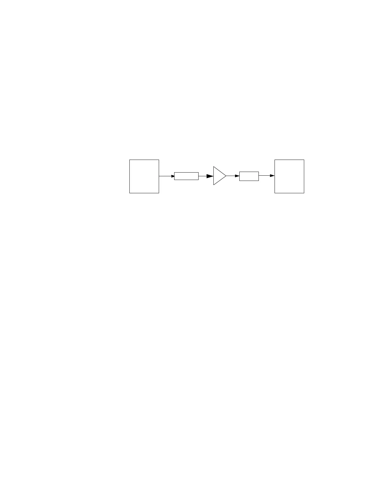
example if you have a test system with a frequency dependent path due to
cable, amplifier or attenuator non-linearities, similar to path illustrated below,
then provided you can quantify the frequency variations, you can apply a
frequency dependent correction to the transceiver source output. In this way
the signal appearing at the receiving device can appear to have the spectral
characteristics associated with a flat path.
The corrections are applied as a table of x and y parameters with the x
specifying the frequency and y specifying the correction to be applied at the
frequency, x. There are four sets of corrections and each may be individually
enabled or disabled. All of the enabled corrections are added together to give
the resultant correction. In the instrument, each port can have four different
corrections applied to it, but two different ports cannot have the same set of
corrections applied to both.
To access the Amplitude Corrections menu press the Input/Output key. Select
the Corrections Tab.
Selecting a port
You can select whether you want to apply the corrections to one of the ports. In
the case of the dual purpose ports, the corrections can be applied to the input,
output or RFIO HD.
To select the port, from the Corrections tab, select Correction Port. You can
select one of the three ports to which the selected corrections apply.
RF Amplifier
Attenuator
transceiver
Source
Output
Cable Loss
Receiving
Device