36 Source User’s Guide
Basic Digital Operation
Using Waveform Markers
This example uses a sine waveform segment in the dual ARB Player.
Factory–supplied segments have a marker point on the first sample point for
all four markers.
1. follow the procedure on page 29 to select and load the waveform segment
file you need.
2. In the ARB Setup menu, Set ARB State to On.
3. Connect the instrument source output to the oscilloscope channel 1 input.
4. Connect the instrument TRIG 2 output to the oscilloscope channel 2
input.
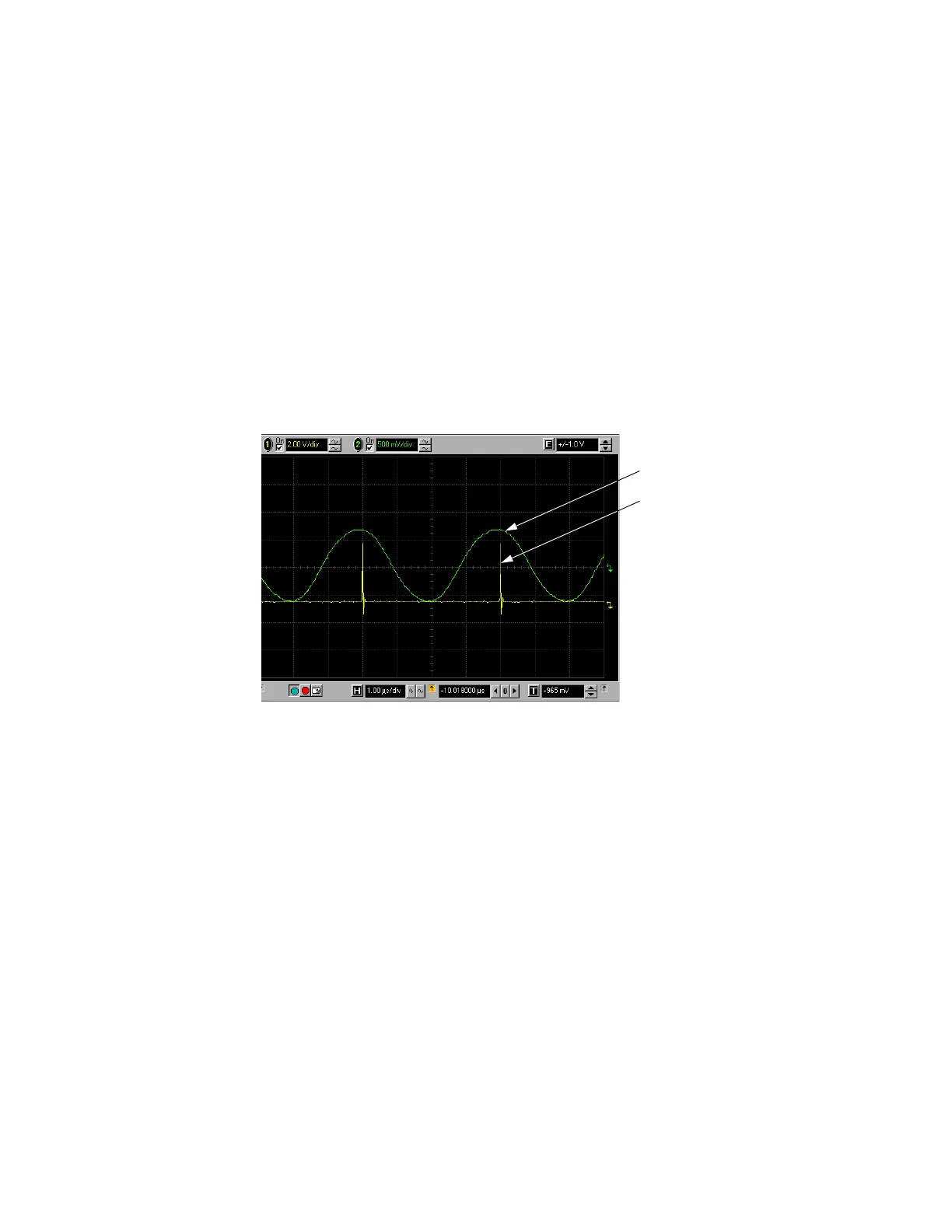
When marker 1 is present, the instrument outputs a signal through TRIG
2 as shown in the following example.
Using the Pulse/RF Blanking Marker Function
While you can set a marker function (described as Marker Routing on the key
label in the Marker Utilities menu) either before or after setting the marker
points, setting a marker function before you set marker points may change the
RF output. The source blanks the RF output when the marker signal goes low.
This example is a continuation of the previous example, “Viewing a Marker
Pulse” on page 35.
1. Using a segment, assume Marker 1 is set across points 1180.
2. From the Marker Routing key menu, assign Pulse/RF Blanking to Marker
1:
In the ARB Setup menu, Click Basic Control, Pulse/RF Blank, Marker 1.
RF OUT
Marker pulse on the TRIGGER 2.