Source User’s Guide 37
Basic Digital Operation
Using Waveform Markers
Setting Marker Polarity
Setting a negative marker polarity inverts the marker signal.
1. In ARB Setup menu, Click Marker Polarity to choose Negative or Positive.
2. For each marker, set the marker polarity as desired.
—The default marker polarity is positive.
—Each marker polarity is set independently.
See also, “Saving Marker Polarity and Routing Settings” on page 35.
As shown on page 36:
Positive Polarity: On marker points are high (3.3 V).
Negative Polarity: On marker points are low (0 V).
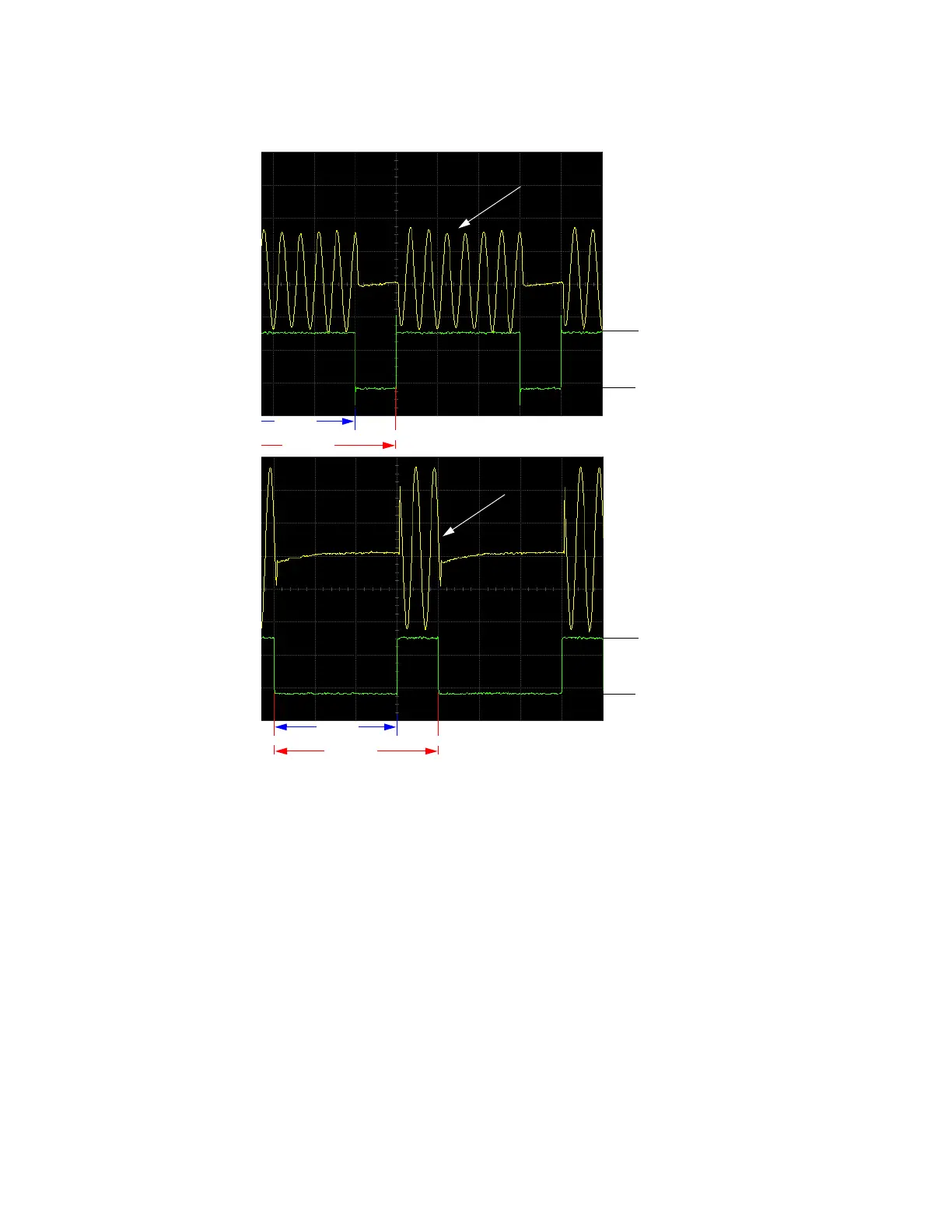
Marker Polarity = Positive
When marker polarity is positive (the default
setting), the RF output is blanked during the off
marker points.
200
180
Marker
Segment
RF Signal
RF Signal
200180
Point 1
Marker
Segment
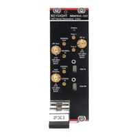
Marker Polarity = Negative
When marker polarity is negative, the
RF output is blanked during the on marker
points
3.3
0 V
3.3
0 V
RF Signal
RF Signal