34 Source User’s Guide
Basic Digital Operation
Using Waveform Markers
Using Waveform Markers
The source provides four waveform markers to mark specific points on a
waveform segment. When the source encounters an enabled marker, an
auxiliary signal is routed to a rear panel trigger output. The marker that is
routed to the TRIGGER 2 connector is selected using the Input/Output menu.
You can use the output signal to synchronize another transceiver with the
waveform, or as a trigger signal to start a measurement at a given point on a
waveform.
You can also configure markers to initiate Pulse/RF Blanking.
When you download a waveform file that does not have a marker file
associated with it, the source creates a marker file without any marker points.
The following procedures demonstrate how to use markers while working with
the ARB player. These procedures also discuss two types of points: a marker
point and a sample point. A marker point is a point at which a given marker is
set on a waveform; you can set one or more marker points for each marker. A
sample point is one of the many points that compose a waveform.
This section also provides the following information:
• “Waveform Marker Concepts
• “Viewing a Marker Pulse” on page 35
• “Using the Pulse/RF Blanking Marker Function” on page 36
• “Setting Marker Polarity” on page 37
Waveform Marker Concepts
The source dual ARB provides four waveform markers for use on a waveform
segment. You can set each marker polarity and marker points (on a single
sample point or over a range of sample points). Each marker can also perform
Pulse/RF Blanking.
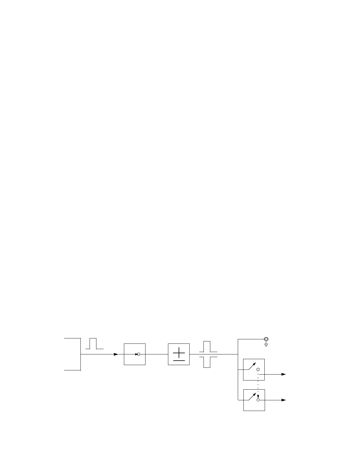
Marker
File
Bit N
Marker
Polarity
Marker N
RF Blank Off On
Marker N
Blanks RF when
Marker is Low
EVENT N
Negative
Positive
Set Marker
On Off
Marker N
ALC Hold Off On
Marker N
Holds ALC when
Marker is Low
When the source encounters an enabled marker (described on page 28), an
auxiliary output signal is generated and routed to the rear panel.
Events 1-4 are available at the TRIGGER 1 connector and at the TRIGGER 2 connector.
RF Blank Only: includes ALC Hold