Keysight CXG, EXG, and MXG X-Series Signal Generators Programming Guide 347
Creating and Downloading User–Data Files
Pattern RAM (PRAM) Data Downloads
memory location. The signal generator’s volatile memory (waveform memory)
storage path is /user/BBG1/waveform. For more information on memory, see
“Signal Generator Memory” on page 321.
The following figure shows a PRAM byte and illustrates the difference between
it and a bit/binary user file byte. Notice the control bits in the PRAM byte.
Only three of the seven control bits elicit a response from the signal generator.
The other four bits are reserved. Table 6-9 describes the bits for a PRAM byte.
As seen in Table 6-9, only four bits, shown in the following list, can change
state:
—bit 0—data
—bit 2—bursting
— bit 6—EVENT 1 rear panel output
— bit 7—pattern reset
Because a PRAM byte has only four bits that can change states, there are only
15 possible byte patterns as shown in Table 6-10. The table also shows the
decimal value for each pattern, which is needed for downloading data using
the list format shown on page 351.
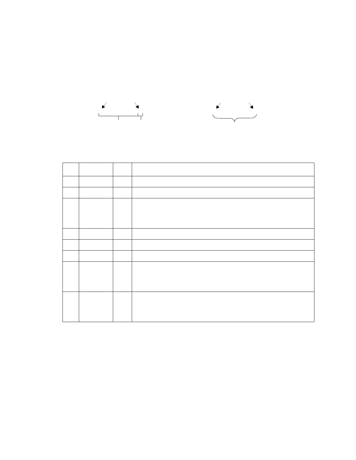
User File Data Byte:
MSB
Data bits
PRAM File Data Byte:
1 1 0 1 0 1 0 1
Control bits
Data bit
LSB
1 0 0 1 1 1 0 1
MSB
LSB
Table 6-9 PRAM Data Byte
Bit Function Value Comments
0 Data 0/1 This is the data bit. It is “unspecified” when burst (bit 2) is set to 0.
1Reserved 0 Always 0
2 Burst 0/1 1 = RF on
0 = RF off
For non–bursted, non–TDMA systems, to have a continuous signal, set this bit to 1 for all
bytes. For framed data, set this bit to 1 for on timeslots and 0 for off timeslots.
3Reserved 0 Always 0
4Reserved 1 Always 1
5Reserved 0 Always 0
6EVENT1
Output
0/1 To have the signal generator output a single pulse at the EVENT 1 connector, set this bit to
1. Use this output for functions such as a triggering external hardware to indicate when the
data pattern begins and restarts, or creating a data–synchronous pulse train by toggling
this bit in alternate bytes.
7 Pattern Reset 0/1 0 = continue to next sequential memory address.
1 = end of memory and restart memory playback.
This bit is set to 0 for all bytes except the last byte of PRAM. To restart the pattern, set the
last byte of PRAM to 1.
 Loading...


