70 X-Series Signal Analyzers Getting Started and Troubleshooting Guide
Using Windows Tools
Remote Desktop: Using the X-Series Signal Analyzers Remotely
Running a Remote Desktop session
Initializing a Remote Desktop session
After setting up the remote computer for Remote Desktop Connectivity, as
described in “Setting up Remote Desktop operation” on page 68, you are
ready to start a Remote Desktop session.
2. Double-click System
The Computer name is listed in the Computer
name, domain, and workgroup settings
section.
Table 4-4 Locating the name from the Windows desktop (with a mouse):
Step Notes
To initialize a Remote Desktop Session, you need to know the Computer Name of the instrument.
Table 4-5 Starting a session
Step Notes
1. Click Windows >
Start menu
>Programs,
Accessories >
Remote Desktop Connection.
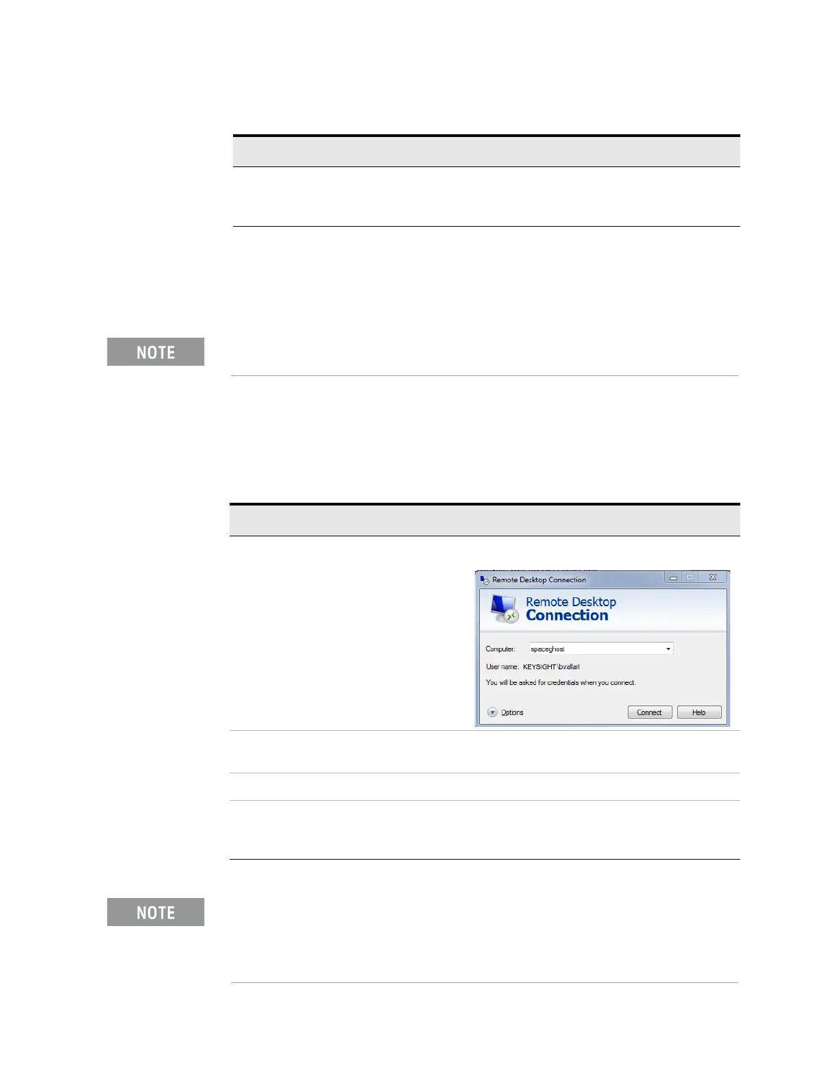
A Remote Desktop Connection dialog appears:
2. Enter the computer name of the
instrument.
3. Click
Connect.
A login dialog box appears.
4. Enter the login account name and
password.
The default account name is Instrument and the
default password is measure4u, but these
parameters may be changed by instrument users.
Only the current User or an Administrator can remotely log into the instrument.
To see who the current user of the instrument is, press
Ctrl+Esc on the
instrument until you can view the current user name on the Start menu. If no one
is currently logged into the instrument, any valid instrument user can remotely log
in.