Do you have a question about the Keysight Technologies U2000 Series and is the answer not in the manual?
Warranty terms, technology licenses, and rights legend for the document.
Explanation of hazard warnings (CAUTION and WARNING) used in the manual.
Product certification, warranty limitations, and exclusive remedies.
Guide to instrument safety symbols and regulatory markings.
Electrical and operational safety precautions for instrument use.
Operating environment requirements and EMC compliance standards.
Information on obtaining the Declaration of Conformity for the instrument.
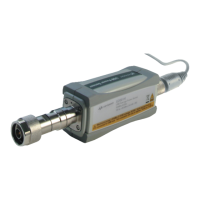
Overview of Keysight U2000 Series USB power sensors and their capabilities.
Details sensor parts, functions, and explanation of LED status indicators.
Explanation of the internal functioning of the power sensor.
In-depth look at the MBID package and sensor technology.
Steps for inspecting the sensor upon receipt and listing included items.
Guidance on hardware setup, including PC and software requirements.
Step-by-step guide for installing the sensor's driver software.
Checks sensor connection and firmware using Keysight Connection Expert.
Steps to configure the sensor's calibration due date.
Explains Average only, Normal modes, and trace display functionality.
Details measurement gate, auto-averaging, and range settings.
Discusses factors affecting accuracy, speed, and range selection.
Explains the two methods for zeroing the power sensor.
Describes automation features for signal source sweeps.
Guidance for measuring pulsed signals in average only mode.
Introduces product specifications and operating conditions.
Explains the difference between warranted and characteristic specifications.
Lists key technical specifications including frequency and connector types.
Details SWR values and provides graphical plots for various models.
Specifies the maximum power handling capabilities of the sensors.
Provides power accuracy specifications and graphical representations.
Defines automatic path selection points and hysteresis.
Details noise and drift specifications for different modes and models.
Describes settling time in FAST, Normal, and x2 speed modes.
Explains calibration factor correction and reflection coefficient.
Lists specifications for internal and external trigger inputs.
Covers physical dimensions, weight, storage, and USB standard.
Overview of maintenance, cleaning procedures, and safety precautions.
Guidance on performing SWR and Rho performance tests.
Lists replaceable parts and provides information on how to order them.
Guidance for resolving issues and repairing defective sensors.
Step-by-step instructions for disassembling and reassembling the sensor.
Specific procedures for attenuator service on U2000B and U2001B models.
Detailed zero set, zero drift, and measurement noise data for specific models.
| Series | U2000 Series |
|---|---|
| Manufacturer | Keysight Technologies |
| Power Supply | USB Powered |
| Power Measurement | True RMS |
| Display | No built-in display, requires PC interface |
| Interface | USB |
| Application | Power monitoring of RF and microwave signals |