Do you have a question about the Keysight Technologies U2004A and is the answer not in the manual?
Defines CAUTION and WARNING notices for hazards and potential risks.
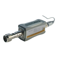
Details the physical components and ports of the USB power sensor.
Explains the working principles and measurement paths of the USB power sensors.
Covers system requirements and steps for installing and configuring the USB power sensor.
Step-by-step instructions for connecting and installing the USB power sensor driver.
Instructions on how to confirm the correct connection and installation of the power sensor.
Guide on setting up the power sensor using the Power Analysis Manager software.
Discusses how to set ranges and factors affecting measurement accuracy and speed.
Explains the two types of zeroing (internal and external) for accurate measurements.
Details how to perform average power measurements for pulsed signals.
Provides the maximum SWR values across various frequencies at standard temperature.
Specifies the maximum average and peak power handling capabilities of the sensors.
Details the power accuracy specifications for average and normal modes.
Specifies zero set, drift, and noise parameters for average and normal modes.
Details on testing SWR and Reflection Coefficient (Rho) performance.
Guidance on diagnosing and resolving common issues with the power sensors.
Instructions for returning a defective sensor for module replacement.
| Category | Accessories |
|---|---|
| Measurement Speed | Up to 1000 readings per second |
| Interface | USB 2.0 |
| Weight | 0.3 kg |
| Type | Power Sensor |
| Power Range | -60 dBm to +20 dBm |
| Calibration | Factory calibrated, traceable to NIST |
| Storage Temperature | -40 °C to +85 °C |