1Getting Started
6 U2000 Series Operating and Service Guide
Principles of Operation
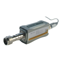
The U2000 Series USB power sensor function as a power meter and
power sensor in one device. The power sensor has the capability of
sensing the signal, acquiring the data and signal conditioning, processing
the data, and fulfilling communication function as in other Keysight test
instruments.
The low power measurement path is a 2- diode stacks and the high power
path contains 5- diode stacks which extend the dynamic range square- law
detection. The range selection is performed automatically by the U2000
Series based on the measured power levels. The sensing element
technology has been previously used in the popular E9300 Series power
sensors. The new U2000 Series includes all the signal conditioning and
analog- to- digital formatting functions that have been in use for several
years. Thus, you can be assured that the U2000 Series USB power sensor
will deliver highly predictable results.
1
The main component for the sensing element of the U2000 Series is the
RF input port assembly which provides a 50 Ω load to the RF signal
applied to the power sensor. A dual range GaAs diode
pair/attenuator/diode pair assembly in the RF input port rectifies the
applied RF signal to produce dc voltages (high and low ranges) which vary
with the RF power across the 50 Ω load. Thus, the voltage varies with the
RF power dissipated in the load.
The low- level dc voltage from the RF input port assembly is picked up by
the signal conditioning part of the sensor which consists of high isolation
switches, chopper circuitry, and high gain amplifier. Differential electronics
is maintained from the sensing element up to the 14- bit Analog- to- Digital
Converter (ADC) for signal integrity and noise immunity. Amplification
and signal conditioning assure that drift and gain stability are not
compromised before hitting the high performance 14- bit ADC modules.
From there, the digitized power data enters the processor which operates
as an on- board computer for the self- contained sensor.
1 Keysight Fundamentals of RF and Microwave Power Measurements (Part 2), Power Sensors and
Instrumentation, Literature Number 5988-9214EN
Anderson, Alan B., October, 2000, Measuring Power Levels in Modern Communication Systems,
MW/RF Magazine