2 Making Measurements
Measuring Resistance
40 U1231A/U1232A/U1233A User’s Guide
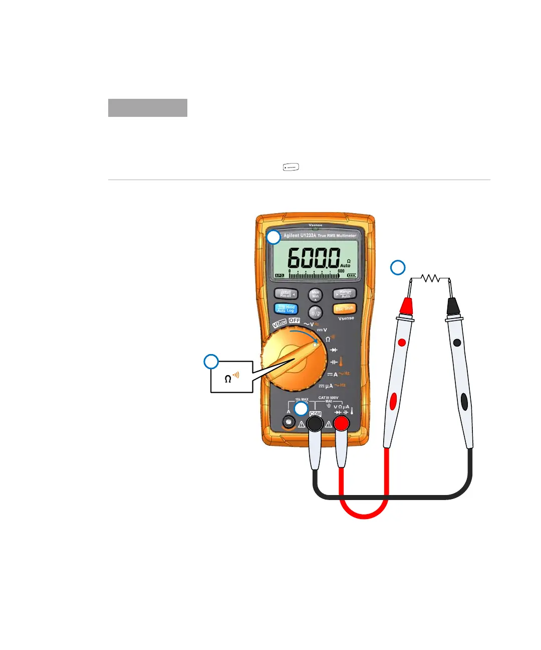
Figure 2-9 Measuring resistance
• Because the multimeter’s test current flows through all possible paths
between the probe tips, the measured value of a resistor in a circuit is
often different from the resistor’s rated value.
• The resistance function can produce enough voltage to forward-bias
silicon diodes or transistor junctions, causing them to conduct. If this is
suspected, press to apply a lower current in the next higher range.