Do you have a question about the Kicker CX SERIES and is the answer not in the manual?
Details on how to mount the KICKER amplifier vertically using specific brackets.
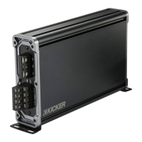
Instructions for connecting power, ground, and signal wires to the amplifier.
Explains the +12V and DC Offset automatic turn-on modes for the amplifier.
Guides setting input level and gain to match source unit and prevent distortion.
Describes the function and use of the fader and sub input selection switches.
Details the variable bass boost feature and its impact on gain settings.
Explains how to adjust the variable crossover frequency for optimal sound.
Instructions for installing the optional CXARC remote bass level control.
Details on how to mount the KICKER amplifier vertically using specific brackets.
Instructions for connecting power, ground, and signal wires to the amplifier.
Explains the +12V and DC Offset automatic turn-on modes for the amplifier.
Guides setting input level and gain to match source unit and prevent distortion.
Describes the function and use of the fader and sub input selection switches.
Details the variable bass boost feature and its impact on gain settings.
Explains how to adjust the variable crossover frequency for optimal sound.
Instructions for installing the optional CXARC remote bass level control.
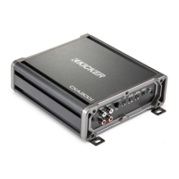
The KICKER CXA660.5 is a versatile multi-channel amplifier designed to enhance your car audio system. This amplifier is part of the CX.5-Series, offering a blend of power and flexibility for various speaker configurations, including a dedicated subwoofer channel. Its primary function is to amplify audio signals from your car stereo's source unit, delivering clear and powerful sound to your speakers and subwoofer.
One of the key usage features of the CXA660.5 is its dual input sensitivity differential RCA inputs. This allows the amplifier to accept both high-level and low-level signals from your source unit. If your source unit only provides high-level speaker outputs, you can easily connect them to the amplifier's RCA inputs using the KICKER KISL (optional) and by setting the Input Level switch to "HI." Alternatively, if your source unit has low-level RCA outputs, you can connect them directly and set the Input Level switch to "LO." This flexibility ensures compatibility with a wide range of car stereos, simplifying the integration process into your existing audio setup.
The amplifier also incorporates an Automatic Turn-On Selection feature, offering two convenient modes: +12V Remote Turn-On and DC Offset Turn-On. The Remote Turn-On mode requires an 18-gauge wire connection from your source unit's remote turn-on lead to the amplifier's REM terminal. For a simpler setup, the DC Offset Turn-On mode automatically detects a >2.5V DC offset from the high-level speaker outputs when your source unit is powered on, eliminating the need for a separate remote wire. This intelligent feature ensures the amplifier powers on and off in sync with your car stereo, providing seamless operation.
For systems with multiple input sources, the Fader Switch is a useful feature. If you are running two sets of inputs (e.g., front and rear channels) to the amplifier, depressing the fader switch allows you to control the fade between these inputs. If you prefer to drive all channels from a single stereo input, simply leave the fader switch in the OFF position. Additionally, the Sub Input switch provides flexibility for subwoofer integration. If your source unit lacks a dedicated subwoofer output, you can set the SUB INPUT switch to either SUB INPUT or AMP INPUT 2, allowing the amplifier to receive the subwoofer signal from an existing channel.
The Input Gain Control is crucial for optimizing the amplifier's performance. It's important to understand that this is not a volume control but rather a mechanism to match the output of your source unit to the amplifier's input level. Proper gain setting ensures maximum power output without distortion and helps prevent damage to your speakers. The manual provides a detailed method for setting the input gain using a voltmeter or oscilloscope, ensuring precise calibration for unclipped power. This involves turning off the amplifier, disconnecting speakers, setting gain and crossovers to their lowest/off positions, playing a sine wave through the source unit, and slowly increasing the gain while monitoring AC voltage at the speaker output terminals. This meticulous process guarantees optimal sound quality and system longevity.
Another notable feature is the variable Bass Boost Control, located on the top panel of the amplifier. This control allows you to increase the output by 0-6dB at 40 Hz, providing enhanced bass response. The setting is subjective and can be adjusted to your personal preference. However, it's important to readjust the input gain control if you increase the bass boost to avoid clipping the amplifier and potential distortion.
The Crossover Control, found on the side panel, offers variable frequency adjustment from 50Hz to 200Hz. This feature allows you to tailor the frequency range sent to your speakers, optimizing sound reproduction and protecting your speakers from frequencies they are not designed to handle. The manual suggests 80Hz as a good starting point for this control, but it can be adjusted to suit your specific speaker setup and listening preferences.
For added convenience, the CXA660.5 supports an optional CXARC Remote Bass Level Control. This accessory allows you to remotely control the output level of the amplifier, providing easy on-the-fly adjustments from your driving position. The remote can be surface-mounted, and connects to the amplifier's "Remote Bass" jack via a 3.5mm patch cable. It's crucial not to connect or disconnect the remote while the amplifier is on, as this can cause the amplifier to output at full gain, potentially damaging your speakers.
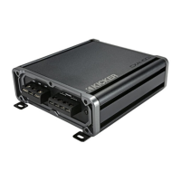
In terms of installation, the CXA660.5 offers space-saving vertical mounting. This feature is particularly useful in vehicles with limited mounting space. To utilize vertical mounting, you would loosen the end panel with a 2.5mm hex key, remove the existing brackets, and then insert and tighten the double-slotted brackets to the amplifier. The manual provides clear illustrations for this process. When choosing a mounting location, it's important to select a structurally sound area that allows at least 4 inches (10cm) of open ventilation to prevent overheating. Mounting the amplifier in the climate-controlled passenger compartment is also recommended for optimal performance and longevity.
Wiring is a critical aspect of installation, and the manual provides detailed instructions to ensure proper and safe connections. It emphasizes disconnecting the vehicle's battery to prevent electrical shorts. The ground wire should be short, 24 inches (60cm) or less, and connected to a paint-and-corrosion-free, solid metal area of the vehicle's chassis. Adding an additional ground wire of the same gauge (or larger) between the battery's negative post and the vehicle chassis is recommended for enhanced grounding. A fuse must be installed within 18 inches (45cm) of the battery and in-line with the power cable connected to the amplifier. For multiple amplifier installations using distribution blocks, each amplifier should have its own proper-rated fuse or breaker installed within eighteen inches of the block, or if the block provides fusing, the primary power wire should be fused between the battery and distribution block, within eighteen inches of the battery's positive terminal, with a fuse or breaker rated at least to the sum of the individual amplifier's fuse values. It's also advised to keep audio signal cables away from factory wiring harnesses and other power wiring to prevent interference, and to cross such wiring at a 90-degree angle if necessary.
Maintenance features primarily revolve around troubleshooting common issues. The amplifier is equipped with Power (PWR) and Protection (PRT) LEDs on the side panel, which indicate the amplifier's status. A green LED signifies that the amplifier is on and operating normally. If the green LED is off and there's no output, the manual suggests checking the +12 volt power terminal, remote turn-on terminal, and ground connections using a Volt Ohm Meter (VOM) to ensure proper voltage and conductivity. If the green LED is on but there's no output, troubleshooting involves checking RCA connections, testing speaker outputs with a known good speaker, substituting the source unit, and checking for a signal in the RCA cable using a VOM meter set to measure AC voltage.
A flickering red LED with loud music indicates low battery voltage, prompting checks of the vehicle's charging system and potentially replacing or charging the battery or alternator. A solid red LED with no output can signal several issues: if the amplifier is very hot, thermal protection is engaged, requiring a check of speaker terminal impedance and airflow. If the amplifier shuts down, voltage protection circuitry is engaged, meaning the voltage is outside the 8–16 volt operating range, necessitating an inspection of the vehicle's charging and electrical system. If the amplifier only plays at low volume levels, short circuit protection is engaged, requiring checks for speaker wires shorted to each other or to the vehicle chassis, or for damaged speakers operating below the minimum recommended impedance.
For issues like alternator noise (whining sound with engine's RPM), the manual recommends checking for damaged RCA (or speaker input) cables, proper routing of these cables, source unit grounding, and ensuring gain settings are not too high. Reduced bass response can often be remedied by reversing a speaker connection from positive to negative on the stereo/subwoofer channel(s), indicating an out-of-phase speaker. Ground noise, while KICKER amplifiers are designed for compatibility, may sometimes require additional grounding of the head unit's RCA outputs to the chassis.
Finally, the manual includes a caution regarding jump starting the vehicle, emphasizing the importance of correct jumper cable connections to prevent blown amplifier fuses and damage to other critical vehicle systems. Overall, the KICKER CXA660.5 is designed to be a robust and user-friendly amplifier, offering a comprehensive set of features for car audio enthusiasts while providing clear guidance for installation, operation, and troubleshooting.