EasyManua.ls Logo

Kidde GSA-REL - Page 34

Kidde GSA-REL
64 pages
Print Icon
To Next Page IconTo Next Page
To Previous Page IconTo Previous Page
Loading...
Chapter 2: Installation
26 GSA-REL Technical Reference Manual
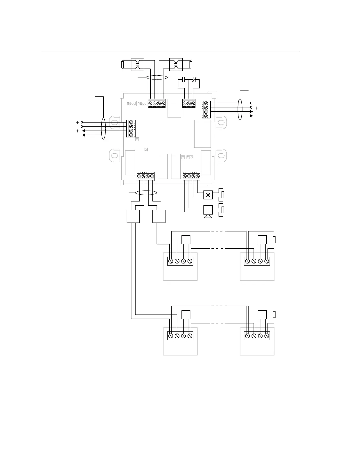
Figure 12: GSA-REL wiring
Wiring diagram notes
[1] Four RELA-EOLs per circuit, max.
[2] Class B, 24 VDC output.
[3] Class B, normally-open manual release station.
1
2
3
4
RELA-EOL
1
2
3
4
RELA-EOL
1
2
3
4
RELA-EOL
TB3
TB2
3
2
1
TB6
4
3
2
1
Releasing Module
TB1
4
3
2
1
TB4
+
_
+
_
3
2
1
4
TB5
3
2
1
4
+
_
+
_
3
2
1
4
1
2
3
4
RELA-EOL
Zone relay output [10]
In
Out
+
_
+
_
+
_
24 VDC in
24 VDC out
Prerelease circuit 2 (steady)
[8] [15]
[2]
[5]
Prerelease circuit 1 (pulsed
15/60/Steady)
[2] [5] [8] [15]
+
_
Class A or Class B
Signature Data Circuit
[8] [13] [14]
[8] [9] Class B
Manual release circuit [12]
[5]
Abort circuit [12]
[5]
[8]
[3]
[4]
[11]
[12]
[1] [2] [7] [8]
[11]
[12]
[5]
Release circuit 2
[6]
[6]
[5]
Release circuit 1
[6]
[6]
Up to 4 devices
per circuit
Up to 4 devices
per circuit

Related product manuals