Chapter 2: Installation
20 GSA-REL Technical Reference Manual
Mounting the GSA-REL
The GSA-REL and the MFC-A require separation between power-limited and
nonpower-limited wiring. See the MFC-A installation sheet for details about
power-limited wiring in that enclosure. See the topic “Wiring the GSA-REL” later
in this chapter for details about power-limited wiring on the GSA-REL.
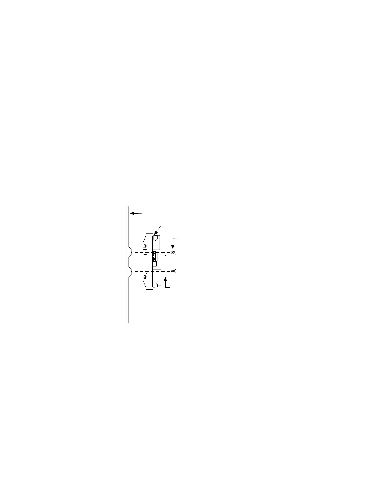
To mount the GSA-REL in an MFC-A cabinet:
1. Align the GSA-REL to the designated mounting holes in the MFC-A (Figure 7
and Figure 8).
2. Secure the GSA-REL to the MFC-A using the screws and washers provided.
3. Run the wiring from the GSA-REL to the fire suppression components
through the conduit knockouts in the MFC-A.
Figure 7: Mounting the GSA-REL
To mount the GSA-REL in other enclosures:
1. Use the GSA-REL to mark the mounting hole locations (Figure 9).
2. Drill the mounting holes at the marks made in step 1 (mounting hole diameter
= 0.125 in or 3.175 mm).
3. Mount the GSA-REL in the cabinet using the screws and washers provided.
#6 Flat washers
6-32 Self-tapping screws
MFC-A
Releasing Module