P/N 3102382-EN • REV 02 • ISS 15DEC16 9
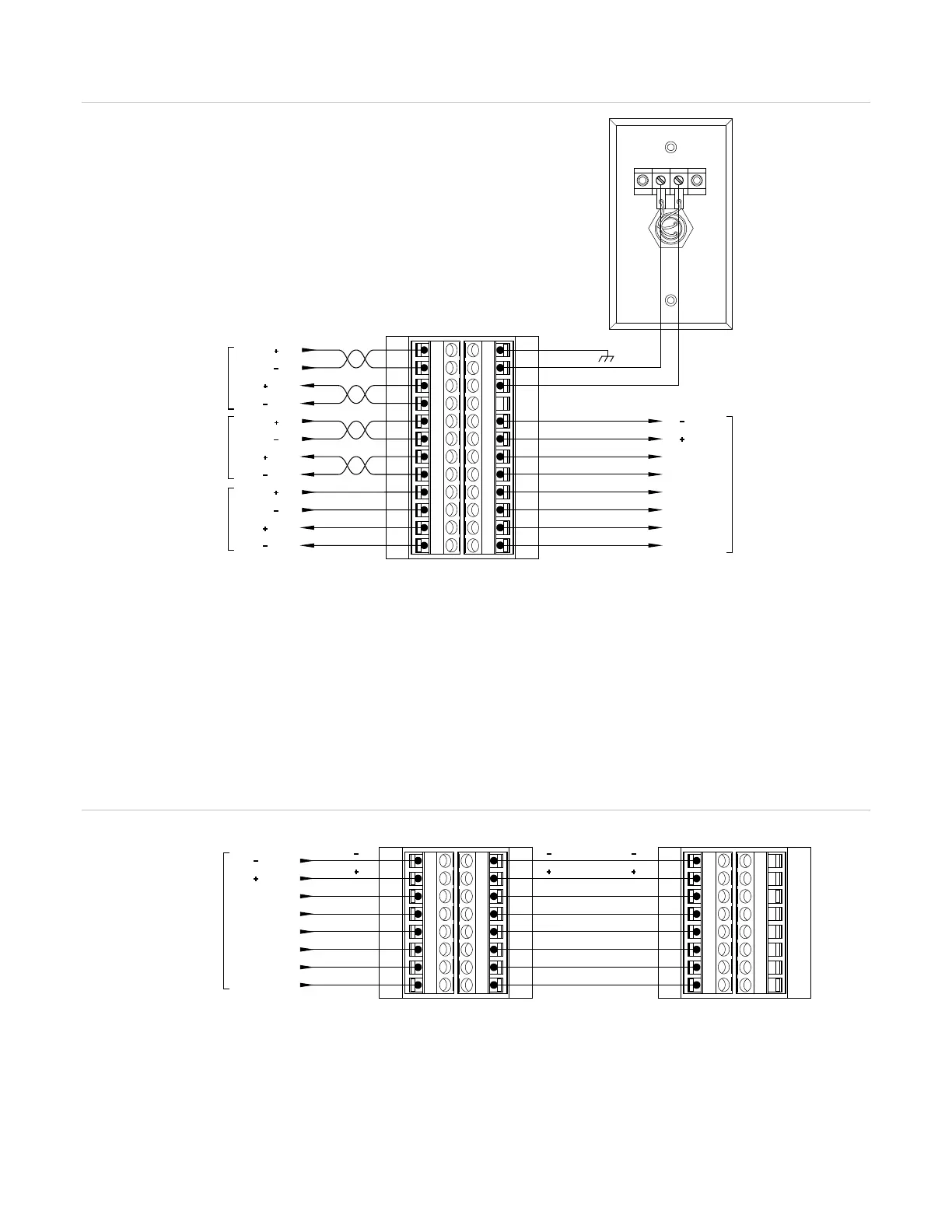
Figure 8: Typical annunciator wiring
(1) CH1_IN+/− from the control panel or previous annunciator. CH1_OUT+/− to the next annunciator or to the
control panel if the last annunciator on a Class A circuit.
(2) CH2_IN+/− from the control panel or previous annunciator. CH2_OUT+/− to the next annunciator. Used only
on redundant Class B circuits. See Figure 6 on page 8.
(3) Use the control panel power supply or a 24 VDC, continuous, regulated, power supply that is UL/ULC Listed
for fire protective signaling systems.
(4) To the expander. See Figure 9.
(5) The remote key switch wiring is not supervised. The key switch must be located within 3 ft. (0.9 m) of the
annunciator and installed in conduit, or equivalent protection against mechanical injury.
A remote key switch is required on K-RLED-C remote annunciators.
Figure 9: Typical expander wiring
K-RLCD(-C) / K-RLED(-C)
Ch1( )_IN
Ch1( )_IN
Ch1( )_OUT
Ch1( )_OUT
24V( )_IN
24V( )_IN
24V
( )_OUT
24V
( )_OUT
RKEY
LOCK(+)
LOCK(- )
EGND
Ch2( )_IN
Ch2( )_IN
Ch2( )_OUT
Ch2( )_OUT
V( )_OUT
V( )_OUT
F_OUT
E_OUT
D_OUT
C_OUT
B_OUT
A
_OUT
(1)
(2)
(3)
(4)
(5)
V( )_IN
V( )_OUT
V( )_IN
V( )_OUT
F
_IN
F_OUT
K-RLED24x
E
_IN
E_OUT
D_IN
D
_OUT
C_IN
C_OUT
B_IN
B_OUT
A_IN
A_OUT
V( )_IN
V( )_OUT
V( )_INV( )_OUT
F_INF_OUT
E_INE_OUT
D
_IND_OUT
C_INC
_OUT
B_INB_OUT
A_INA_OUT
K-RLED24x
K-RLCD(-C)
or
K-RLED(-C)