INSTALLATION OF SCALE UNIT
HITCH ASSEMBLY
1. Remove the 3/4” x 5” bolt (102520),
lockwasher (100186), and nut (102521) to
remove the swivel hitch (102524.)
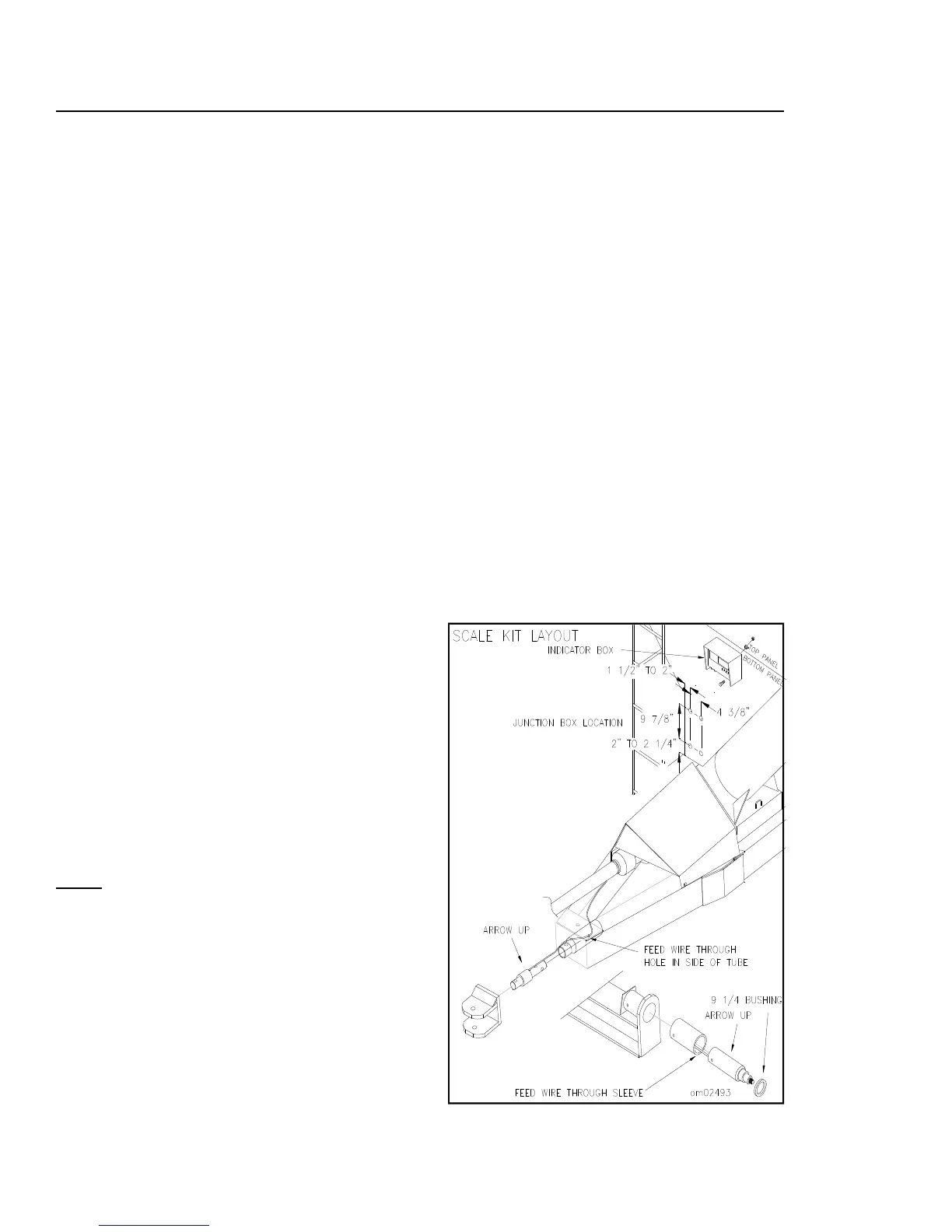
2. Before installing the 2-1/8” weigh bar
(102694), insert scale bushing. Feed the
wire into the hitch tube, through to the
hole in side of bushing, see Fig. 5. Insert
the 2-1/8” weigh bar.
3. To secure weigh bar to hitch reattach
hardware removed.
JUNCTION BOX INSTALLATION
1. Install Junction Box on the back side of
the right front frame standard (see Fig. 6.)
2. See page 13 for specific wiring installation
instructions.
SPINDLE ASSEMBLY
1. Use a 5 ton jack, or more, and jack
stands to support the weight of your grain
cart. Place the jack stands under the axle
near the tire.
2. Remove the tire and hub assembly.
3. Remove the bolt, lockwasher, and locknut
to release the 3-3/8” or 4-1/2” dia. spindle.
4. Change the grease seal in the hub.
5. Using the same bolt, lockwasher, and lock-
nut just removed, add the spindle bushing
and 2-7/8” or 3-3/4” dia. scale spindle.
6. Attach hub assembly and original wheel
and tire.
NOTE: Tighten lug nuts to 400 ft. Lbs.
INDICATOR INSTALLATION
The location of the indicator box is optional.
The indicator box may be mounted in the cab
of the tractor or on the front of the Grain
Cart. For tractor cab installation mount the
indicator box in the best location suitable to
the operator. Run the appropriate wires for
electrical hook-up. (Refer to pg. 13.) For the
installation on the front of the grain cart follow
these steps.
FOR HARDWARE LISTING
SEE PG. 26
Fig.6
NOTE: For protection against the environment.
It is recommended that the indicator be
mounted in tractor cab when applicable.
1. Locate Indicator Box on top side of right
front frame standard. *Note: Be sure that
the junction box is not directly located
behind indicator while drilling holes.
2. Indicator should be placed at eye level
toward top of panel for convenient, effi-
cient use. (See Fig. 6)
3. Mark cart for drill holes while holding indi-
cator in place. Be sure hole alignment is
level before drilling holes.
4. Drill holes and secure with hardware pro-
vided. Hook up all necessary wires to
operate scale. (Refer to pg. 13.)