4
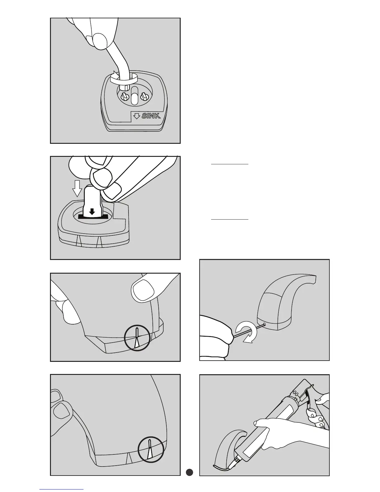
12. Use the hand tool provided to complete
the tightening of the support shaft.
Tighten in a clockwise direction (see
gure 11).
13. Push the signal cable attached to the
soap discharge head thru the opening in
the support shaft (see gure 12).
14. Align the notches on the bottom of the
soap discharge head with the tabs on the
support shaft (see gure 13).
15. Rotate the soap discharge head counter
clockwise until the tab on the soap
discharge head is aligned with the rear
tab on the support shaft (see gure 14).
16. IMPORTANT – Using the Allen wrench
provided, tighten the set screw clockwise
on the back of the soap discharge head
until it is tight. The head of the set screw
should be ush to below the surface of
the soap discharge head. (see gure 15).
17. IMPORTANT – Apply a bead of clean
silicone caulk around the perimeter of
the support shaft / head assembly (see
gure 16).
Fig. 12
Fig. 13
Fig. 14
Fig. 16
Fig. 15
Fig. 11