Chapter 3 Installation Environment
45
Chapter 3 Installation Environment
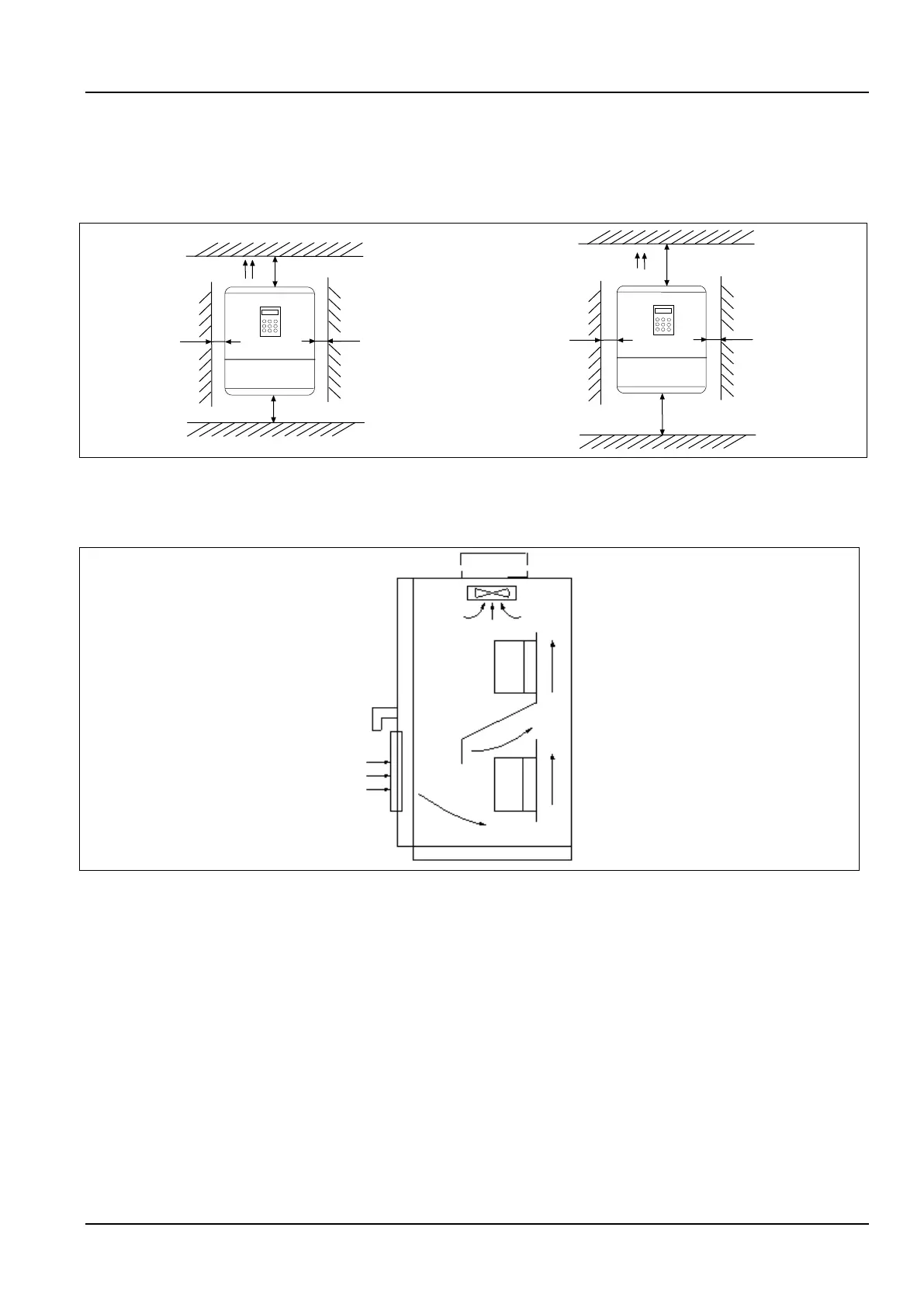
The requirements on mounting space and clearance are shown in Fig. 3-1 and Fig. 3-2.
Fig 3-1 Installation interval (Power below 45kW)
Fig 3-2 Installation interval(Power above 55kW)
When two VFD are mounted and one is on the top of another, an air flow diverting plate should be fixed in between
them as shown in Fig. 3-3.
Fig 3-3 Installation of several VFD

 Loading...
