Kinco-HP
User Manual
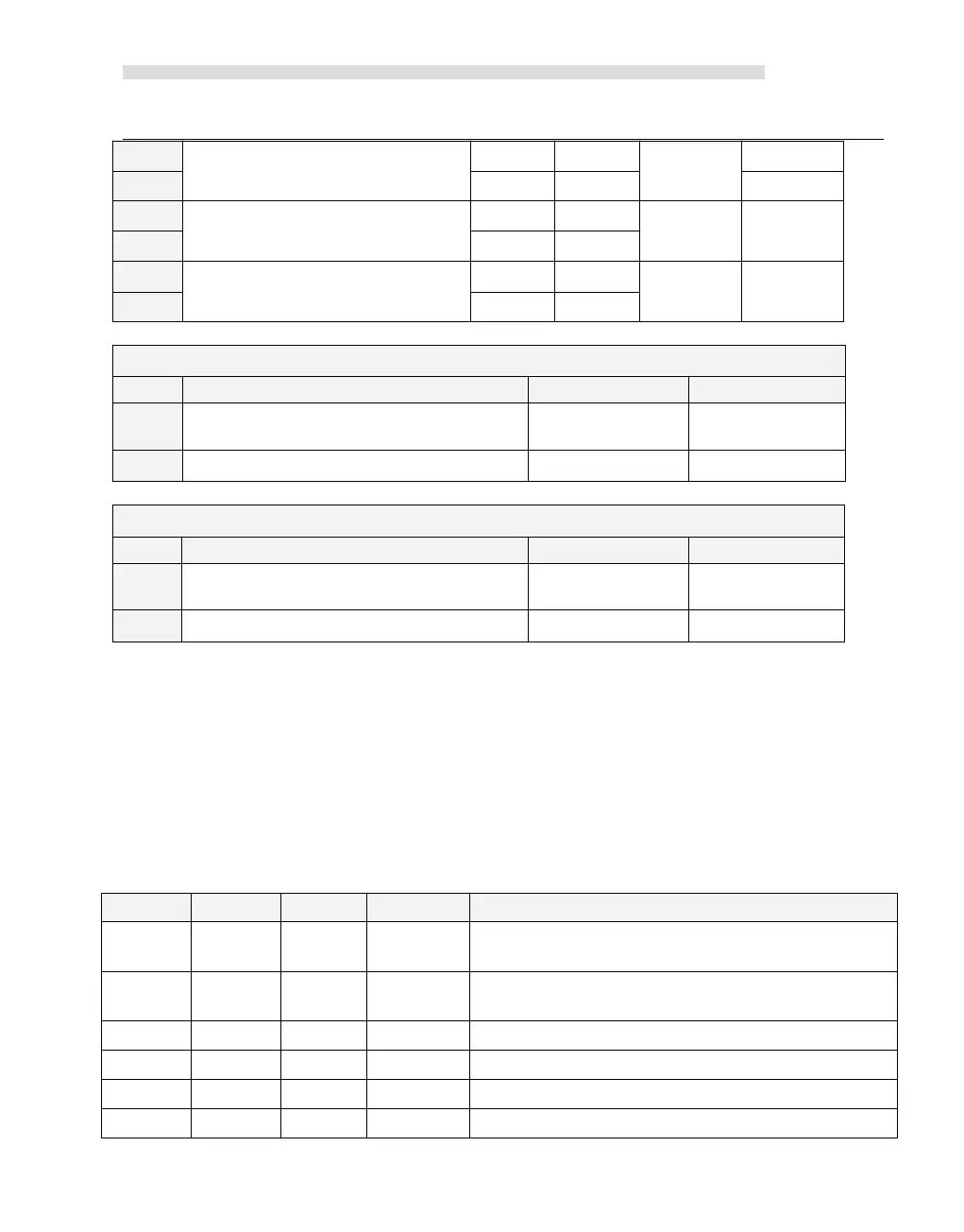
Single-phase up/down counter
with external direction control
Two-phase counter
with up/down clock inputs
A/B phase quadrature counter
Single-phase up/down counter
with internal direction control:SM57.3
A/B phase quadrature counter
Note: HP043-20DTC's HSC2 only supports mode 0, and the input is I0.4.
Single-phase up/down counter
with internal direction control:SM127.3
A/B phase quadrature counter
3.2.3.2 Control Byte and Status Byte
Control Byte
In SM area,each high-speed counter is assigned control byte to save its configuration data: one
control word (8 bit), current value and pre-set (double-integer with 32 bit). Initial value of
current assigned value. If the current value is written in the high-speed counter, it will start
counting from that value. Please see below:
Effective electrical level of reset signal:0=high;
1=low
Effective electrical level to start signal:0=high;
1=low
Orthogonal counter rate:0=1x rate;1=4x rate
*
Counting direction:0=Decrease;1=Increase
Write counting direction in HSC? 0= NO; 1= Yes
Write new pre-set value in HSC? 0= NO; 1= Yes