Kinco-HP
User Manual
3.3.1 Wiring diagram
Please refer to 2.2 Wiring diagram
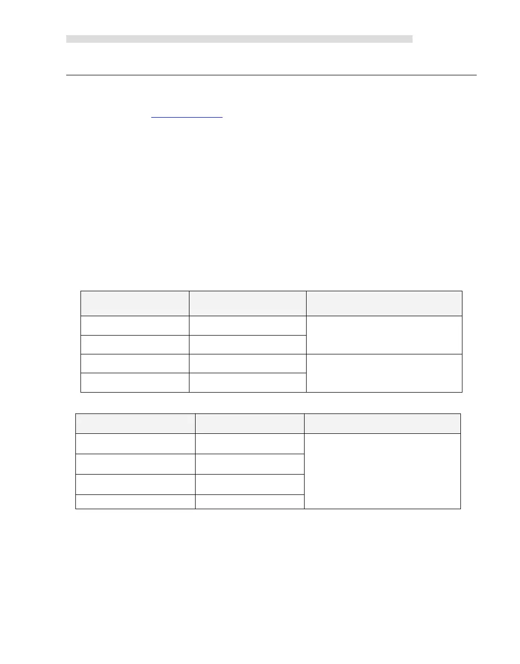
3.3.2 Measurement Ranges and The measured value Representation
The input signal in each channel will sample ADC and counter. The results will be send to
CPU AI area from expansion CAN. Then user programming can visit it.
All the signal types have detection range. If the value is over range, the modules will warn,
Meanwhile it will send problem file to CPU by expansion module. Pls connect all the
channels that is not used, also setup signal type to 【0-10V】,then these channels won’t
warn.
In the following table, I stand for current,while V represents input voltage value, unit V.
In the following table, T represents measured temperature, unit:°C.
The AQ output value specified in the user program would firstly sent to the corresponding AO
module through the expansion bus, and then calculated, transformed, and output on the
specified channel through the DAC.
The signal output range are limited.If the user assign an output value over the limitation,The
actual output value would keep maintain on the upper or lower limit value.