K
K
K
K inco
inco
inco
inco -K
-K
-K
-K S
S
S
S series
series
series
series
25
positioning) ,PHOME(Homing), PJOG(Jogging) and PSTOP(Emergency stop). User can use these
instructions to achieve positioning control easily . Note:
Note:
Note:
Note: When
When
When
When using
using
using
using position
position
position
position control
control
control
control instructions,
instructions,
instructions,
instructions, the
the
the
the
frequency
frequency
frequency
frequency of
of
of
of output
output
output
output pulse
pulse
pulse
pulse must
must
must
must be
be
be
be not
not
not
not less
less
less
less than
than
than
than 125Hz.
125Hz.
125Hz.
125Hz.
3 ) Following instruction PFLO_F: There are parameters such as input frequency (
F
) ,electronic gear
ratio (
NUME 、 DENOM
) , pulse number(
COUNT
) and so on, these parameters can be used as variable.
The frequency of pulse output is equal to
F
multiple by electronic gear ratio. When the pulse number
reaches the value
COUNT
, then it will stop output and set
DONE
bit. Note:
Note:
Note:
Note: When
When
When
When using
using
using
using following
following
following
following
instruction,
instruction,
instruction,
instruction, the
the
the
the frequency
frequency
frequency
frequency of
of
of
of output
output
output
output pulse
pulse
pulse
pulse must
must
must
must be
be
be
be not
not
not
not less
less
less
less than
than
than
than 30Hz.
30Hz.
30Hz.
30Hz.
2.3.2
2.3.2
2.3.2
2.3.2 How
How
How
How to
to
to
to use
use
use
use PLS
PLS
PLS
PLS instruction
instruction
instruction
instruction
PLS instruction can implement PTO and PWM output function.
• PTO : Pulse Train Output .
•
PWM
:
Pulse-Width Modulation.
�
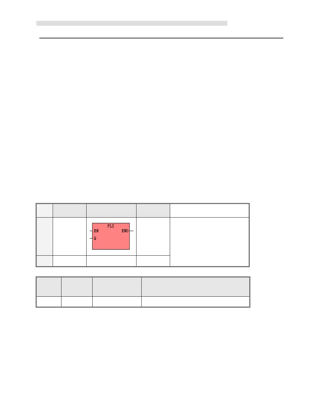
Descriptions
Name
Name
Name
Name Usage
Usage
Usage
Usage Group
Group
Group
Group Suitable
Suitable
Suitable
Suitable for
for
for
for
LD
LD
LD
LD PLS
K2
K5
IL
IL
IL
IL PLS PLS
Q
U
Operan
Operan
Operan
Operan
ds
ds
ds
ds
Input/Out
Input/Out
Input/Out
Input/Out
put
put
put
put
Data
Data
Data
Data Type
Type
Type
Type Description
Description
Description
Description
Q
Input INT Constant ( 0 、 1 or 2 )
The PLS instruction is used to load the corresponding configurations of the PTO/PWM from the specified
SM registers and then start outputting pulse until it finish outputting pulse. The pulse output channel is
specified by parameter Q, 0 means Q0.0,1 means Q0.1,2 means Q0.4.
Note: In user program, it only needs to execute PLS instruction once when it is required. It is suggested to use

 Loading...

