16
EN
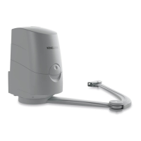
3.5 - Installation of the fixing brackets
and the gear motor
3.5.1 – Installation of the rear fixing
bracket
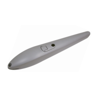
Calculatetherearbracketpositionusingchart 2.
Chart 2 (mandatory measurements)
100
150
200
250
300
350
400
450
100 150 200 250300 350
100°-110°
110°-120°
95°-100°
90°-95°
This chart is used to dene distances A and C and the leaf
maximum opening angle.
A
398
MO LINK 420
MO LINK 180
max 655 mm
AC
140 30 90
250 30 110
140 80 90
185 80 100
140 130 90
170 130 95
140 160 90
160 160 95
140 200 90
150 200 90
140 240 90
150 240 90
140 280 90
170 280 90
140 320 90
170 320 90
MO LINK 180
AC
140 30
250 30
140 80
190 80
140 130
170 130
140 160
160 160
140 200
160 200
MO LINK 420
max 800 mm
90
120
90
100
90
100
90
95
90
95
1
1
1
Fig. 3
01. Measurevalue“C”,thentraceastraighthorizontallineinchart
1againsttheobtainedvalued.Selectapointintheline,takinginto
accountthedesiredopening angle, suitable for the column.Trace
avertical linestartingfromthepointidentiedand obtainvalueA.
Beforeproceedingwiththeinstallation,makesurethatvalueAallows
toxtherearbracket,otherwiseselectanotherpointonthechart.
Finally,toxthebracketontheleaf,refertothemaximumdimensions
ofthearmingure3.Failuretocomplywiththebracketinstallation
distancesmayleadtoautomationoperationfaults,suchas:
- Cyclical movements and accelerations at some positions of the
stroke.
-Increasedmotornoise.
-Limitedopening,ornoopeningatall(incaseofcounter-leverxed
motor).
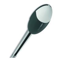
WARNING!–Beforexingtherearbracket,makesurethat
thefrontbracketwillbexedtoasolidpositionofthegate
leaf; the front bracket will have to be secured at a different
height than the rear bracket (Fig. 4).
5 mm
Fig. 4
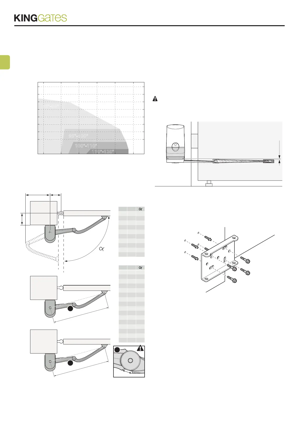
02.Atthispoint,markontheleafandonthewalltheholesofthe
bracketswhichwillthenbeusedtoxthetwobrackets.
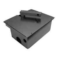
03. Fixtherearbracketofthemotortothewallcomplyingwiththe
dimensionsseenpreviously(g.5).
Fig. 5
Installation
examples