25
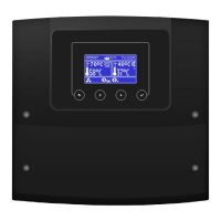
The controller terminals box:
Connecting cables to the controller: 1 - cable clamps, 2 - cable clamp screws, 3 - voltage cables (mains 230 VAC), 4 -
safe voltage cables (signal, below 15 VDC), 5 - mains cable connector 230 VAC, 6 - signal wires connector, 7 - protective
wires connector.
The maximum length of the external tire insulation cannot exceed 50 mm.
Before screwing the controller terminal cover, arrange the wires so that their insulation
is not damaged by cutting the cover edge or by screws securing the cover. Excess
wires in the terminal box are not allowed.
In case of using the version with STB device before making the montage and wiring it is strongly
recommended to take out the (2) STB capillary from inside the clamp box using (1) catch as
show on the picture below.
Description: 1 - catch, 2 – STB capillary cable, which was being correctly taken out from the clamp box.
Attention! This capillary cannot be smashed or bend with acute angle.
 Loading...