PT260 Service Manual
4
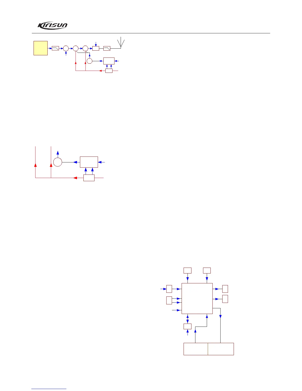
ANT SW
RF PA
RF PA
DRIVER
DRI VER
PRE
5T
5T
APC
SW
APC
CONTROL
APC FROM MCU
CURRENT
SENSING
POWER SUPPLY
RDA1845
Figure 3.2 Power Amplifier and Antenna Switch Diagram
The modulated RF signal from IC1 (RDA1845) is amplified
by Q19 and Q22, and then is sent to Q21 for power amplifier. The
output power of Q21 is 4.5W.
Grid bias of Q21 and Q22 is controlled by the APC circuit.
By changing the voltage of grid bias, the TX output power can be
controlled conveniently.
APC (Automatic Power Control)
APC
SW
APC
CONTROL
APC FROM MCU
CURRENT
SENSING
POWER SUPPLY
Figure 3.3 APC Circuit Diagram
R231, R232 and R233 are used to test the power amplifier
current. IC3A is the sampling amplifier for the power amplifier
current. IC3B is the power comparator amplifier.
If the TX output power is too high, the power amplifier
current and IC5A output voltage increase; IC5B output voltage
decreases, and the offset voltage added to Q21 and Q22 decreases,
which cause the TX output power decreases and vice versa. Thus,
the TX output power can keep stable under different working
conditions.
By changing the voltage inputting to IC5B, the MCU can
adjust the power.
TX Voice Signal Process
MIC signal passes through the inner and outer MIC Switch
Circuit. This signal first is sent to U32U for filter and amplifier, and
then is sent to the 5
th
pin of IC1 (RDA1845) for carrier modulation.
3.4 Principle of Frequency Synthesizer
13MHz reference frequency signal provided by X1 is sent to
the internal reference divider of IC1 (RDA1845) for division, and
then is sent to the internal discriminator and the internal VCO to be
divided by decimal fraction divider, and then this signal comes to
phase comparator. The internal VCO is controlled by the output
control signal to make the frequency of VCO equals to the
designed frequency.
3.5 Voice Annunciation Circuit
This product has voice annunciation function, which is
especially useful at night or in the dark environment.
IC2 is the voice storage chip, which stores voices such as
channel annunciation and so on. When switching to the next
channel, the radio will annunciate the current channel number.
When pressing “Voice Annunciation” Key, the radio will
annunciate the channel number again.
If Voice Annunciation is enabled, press “Voice Annunciation”
Key in the standby state, the radio will annunciate the current
channel number. Press and hold that key to restart the radio and
change the type of voice annunciation. When repressing the key to
restart the radio, the radio will annunciate again and again in the
order of “Chinese woman voice-English woman voice-no sound”.
3.6 Power Supply
The radio uses 7.4V, 1100mAh Li-on battery as the power
supply. The transmitter power amplifier circuit (Q21, Q22) and the
receiver audio power amplifier (U31) directly adopt the battery for
power supply. Other circuits are powered by 3V regulated voltage.
IC6: 3V low dropout, micro-power regulator, supplies 3V
voltage for the radio.
Q12: 3T switch, controlled by MCU.
3T: Supplies power for front end of the TX.
Q27: 3R switch, controlled by MCU.
3R: Supplies power for RF amplifier, mixer, IF processing
unit, and audio signal processing unit etc. of receiver.
3.7 MCU Unit
MC U
M30C026FPG#U0
7.3MHz RES ET
EEPR OM
3M
3M
3M
E NCODE R KE YS
KEYAD
MODE
PTT
SHIFT QTOUT
PABC
DTAT
CLK LE
3RC
TXD
RXD
AFC O
APC
MUT E
3TC
QTIN
SQL
BATT
W558C
CFA
WDATA
WSCLK
G/R LED RDA 1845

 Loading...