PT260 Service Manual
3
2.2 Functional Keys
① LED indicator
Red LED lights in transmitting; Green LED lights in
receiving. Red LED flashes in low battery warning.
② Channel selector
Rotate it to select channel 1-16.
③ Power ON/OFF/Volume knob
Rotate it clockwise until a click is heard to power on the radio.
Rotate it counterclockwise until a click is heard to power off the
radio. Rotate it to adjust the volume.
④ PTT button
Press it and speak to the microphone to send a call. Release it
to receive a call.
⑤ Monitor
Press it to turn off the squelch circuit, and then the user can
hear the background noise. Release it to turn on the squelch circuit.
⑥ Voice annunciation
In standby state, press this key and the radio will annunciate
the current channel number. Press it again to restart the radio and
change the type of annunciation.
⑦ Emergency button
Press this key and an alert tone sends out. Press it again to
turn off the alert tone. All the other switches and keys are invalid in
this state.
⑧ Speaker/Microphone jack
Use it to connect the external speaker and microphone.
Chapter 3 Circuit Description
3.1 Frequency Configuration
The receiver adopts single mixing. The first IF is 9.375 kHz.
The first local oscillator signal of the receiver is generated by
the frequency synthesizer. The transmitter signal is generated by
the frequency synthesizer.
The reference frequency of the frequency synthesizer is
produced by TXCO.
3.2 Principle of Receiver (RX)
RF
AMP
5R
RDA1845
ANT SW
5T
FROM TX
AF POWER AMP
AF
MUTE
MUTE
1
23
4
5
W55 8
AF
MUTE
5M
AF
AMP
GND
AF
POWER
AFC N
POWER
SW
3
3
4
4
2
2
1
1
2
SPK J ACK
TXD
GND
BAT T
3A
sw
CLK FROM MCU
DATA FROM MCU
BUS Y TO MCU
MUTE
DTMF/BEEP FROM MCU
5C
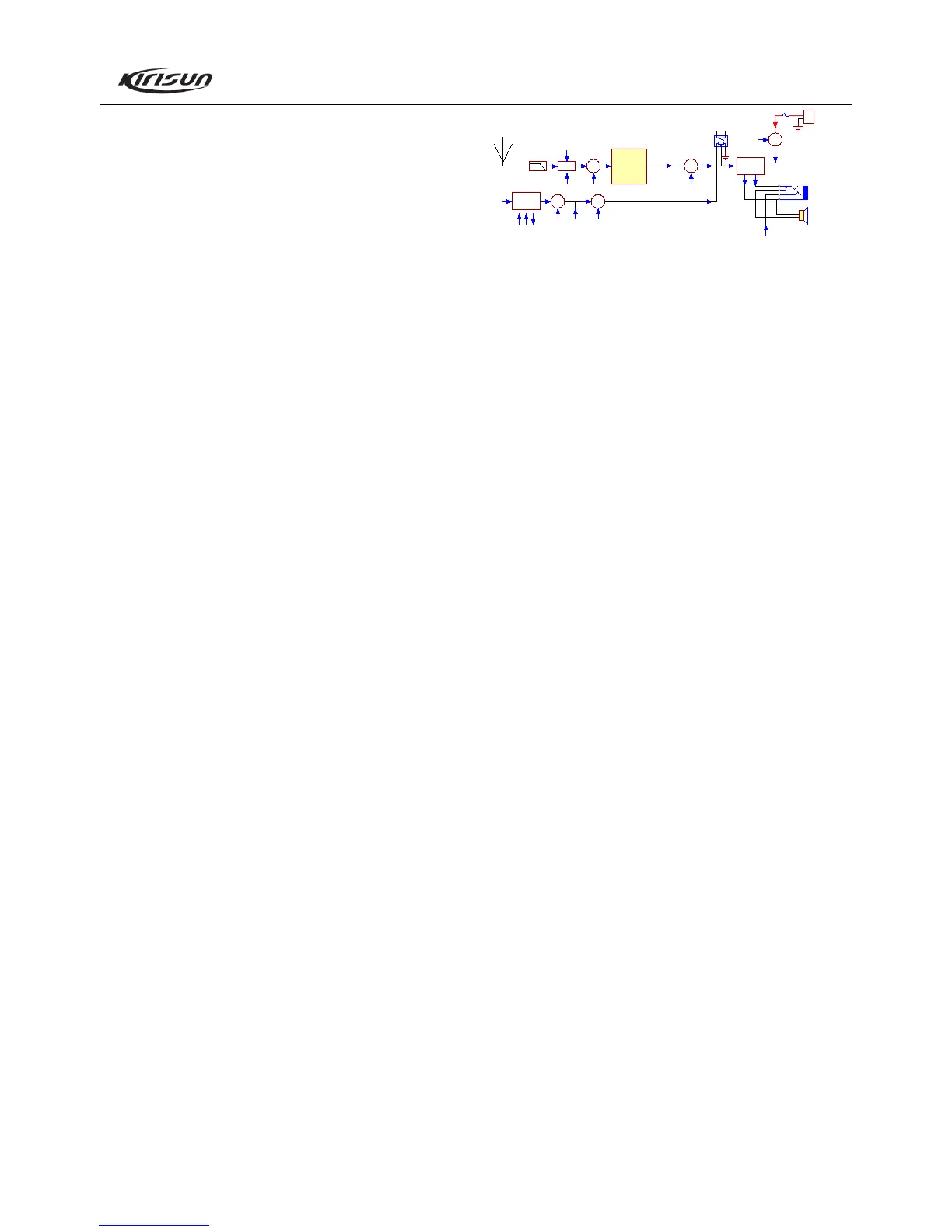
Figure 3.1 Receiver Diagram
Receiver Front End
The signal coming from the antenna passes through the
RX/TX switch circuit (D11, D12, D21, D17), and sends into IC1
(RDA1845) to demodulate, and then output audio signal.
RX Audio Signal Process
The audio signal demodulated by IC1 (RDA1845) passes
through the volume potentiometer, and comes to audio power
amplifier U31 (TA7368F).
Squelch Circuit
The third pin of IC1 (RDA1845) sends out signal to MCU
which can identify the noise level and control the squelch circuit.
Audio Power Amplifier
IC1 and the periphery components consist of BTL audio
power amplifier circuit.
Base electrode of Q31is the control end. High level: On; low
level: Off.
Receiving audio signal, voice annunciation signal, alert tone
signal and emergency alarm signal gather together and are
amplified by audio amplifier to drive the speaker. Among these
signals, the emergency alarm cannot be adjusted by the volume key.
The impedance of the speaker is 8 Ω.
CTCSS Process
The 33
rd
pin of IC1 (RDA1845) outputs CTCSS/CDCSS signal to
MCU to decode.
3.3 Transceiver (TX) Principle
TX Amplifier

 Loading...