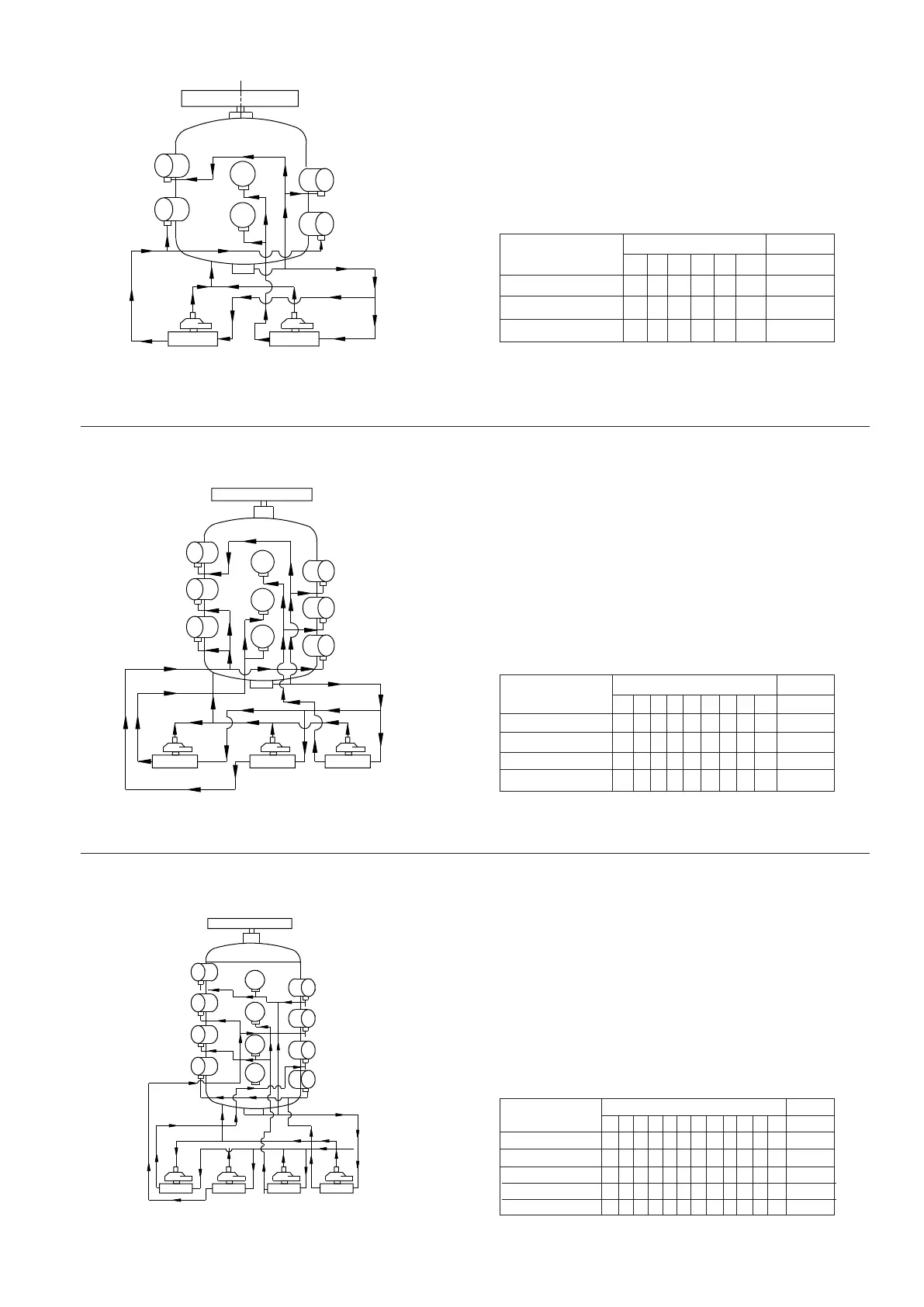
Compressor KC-6 Figure 12
Cyl. Block. No. Capacity
1 2 3 4 5 6 %
Direct Connection 4- - - - 33
Solenoid Valve 1 ON 444- 4- 67
Solenoid Valve 2 ON 444444100
4
1
2
3
4
5
6
S.V.NO.2 S.V.NO.1
1 2 1 2
Compressor KC-9 Figure 13
Cyl. Block. No. Capacity
1 2 3 4 5 6 7 8 9 %
Direct Connection 4- 4- - - - - - 22
Solenoid Valve 1 ON 444- - 4- - - 45
Solenoid Valve 2 ON 4444- 44- 478
Solenoid Valve 3 ON 444444444100
1
2
3
4
5
6
7
8
9
1 2
1 2 1 2
S.V.NO.3 S.V.NO.2 S.V.NO.1
Compressor KC-12 Figure 14
Cyl. Block. No. Capacity
1 2 3 4 5 6 7 8 9 10 11 12 %
Direct Connection 444- - - - - - - - - 25
Solenoid Valve 1 ON 444- - - - - - 4- 442
Solenoid Valve 2 ON 444- 4- 44- 4- 467
Solenoid Valve 3 ON 44444444- 4- 483
Solenoid Valve 4 ON 444444444444100
3 3
3 3 3
1
2
3
6
5
4
7
8
9
11
10
12
S.V.NO.4 S.V.NO.3 S.V.NO.2 S.V.NO.1
1 2 1 2 1 2 1 2
3333
15