16
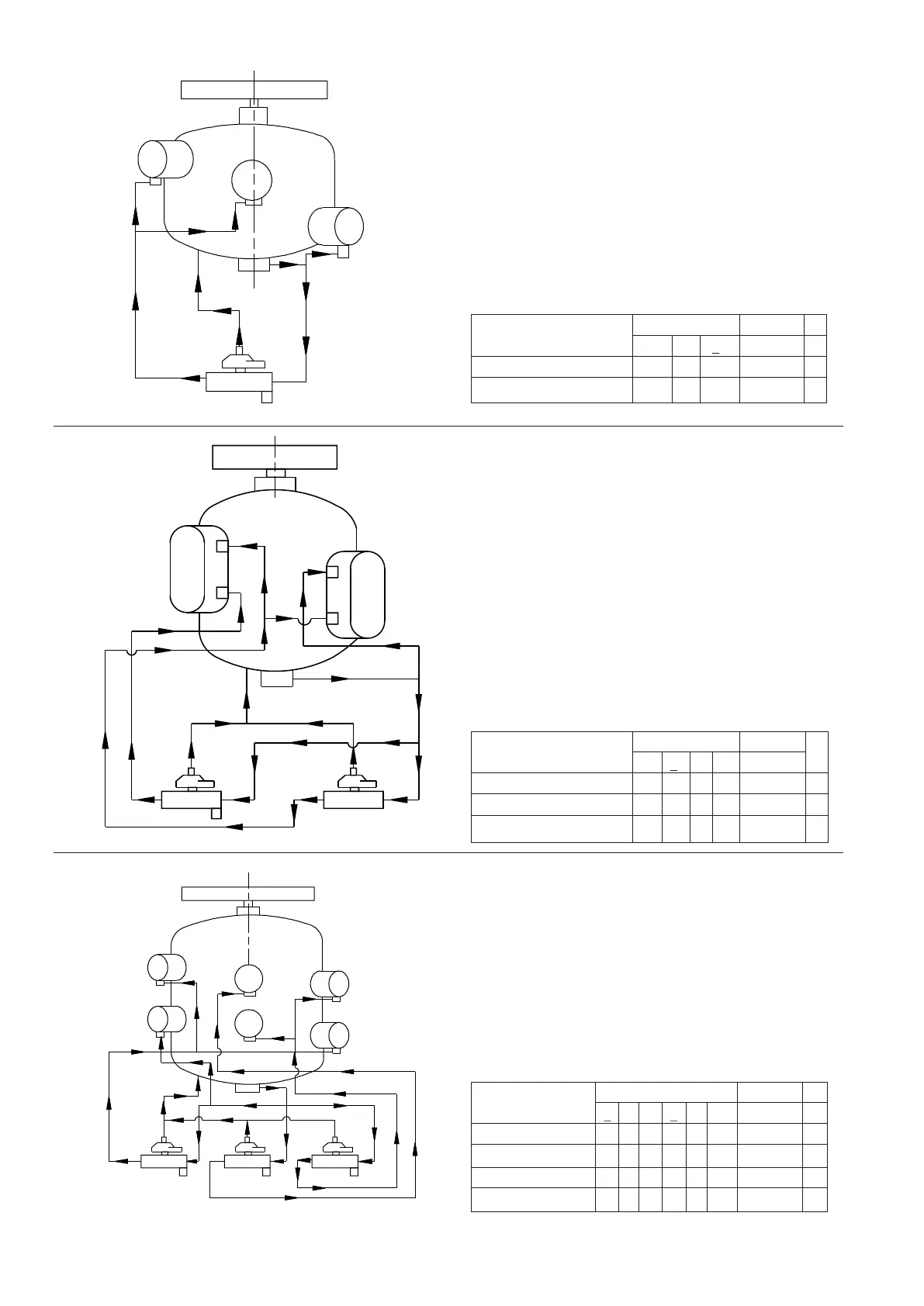
Compressor KC-21 Figure 15
Cyl. Block. No. Capacity Ø
1 2 3 % -
Direct Connection - - 4- -
Solenoid Valve ON 444100 2
1
3
2
4
1
3
2 1
3
2
S.V.NO.2
S.V.NO.1
Cyl. Block. No. Capacity Ø
1 2 3 4 % -
Direct Connection - 4- - -
Solenoid Valve 1 ON 44- 467 2
Solenoid Valve 2 ON 4444100 3
Compressor KC-31 Figure 16
Cyl. Block. No. Capacity Ø
1 2 3 4 5 6 % -
Direct Connection - - - 4- - - -
Solenoid Valve 1 ON - - 444- 50 2
Solenoid Valve 2 ON - 4444- 75 3
Solenoid Valve 3 ON 444444100 3
Compressor KC-42 Figure 17
2
3
1 2
1
HP
3
HP
1 2
HP
HP
1
2
3
4
5
6
1 2 1 2
3 3 3
S.V.NO.1 S.V.NO.2 S.V.NO.3
CAPACITY CONTROL DIAGRAMS
(TWO STAGE)