Do you have a question about the Kistler 5015A Series and is the answer not in the manual?
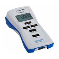
Specifies the model of the charge meter and its capabilities.
Details the specific firmware versions for the instrument.
Provides contact and company details for Kistler Group.
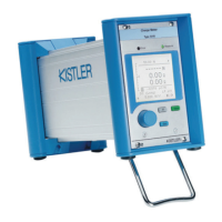
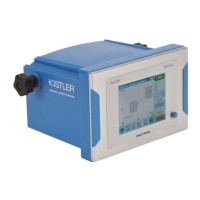
Introduces the Kistler Charge Meter Type 5015A... and its features.
Lists other Kistler products for measuring technology.
Information on Kistler customer service and distributors.
Essential safety precautions for operating the Charge Meter.
Instructions for unpacking the instrument and checking contents.
Guidelines for safely transporting and storing the instrument.
Procedure for selecting the correct supply voltage for the instrument.
Information regarding the instrument's compliance with EMC standards.
Advice on how to effectively read and use the instruction manual.
Lists the accessories that are supplied with the Charge Meter.
Lists optional accessories available for the Charge Meter.
Explains abbreviations, symbols, and typefaces used in the manual.
Defines units of measure and the International System of Units (SI).
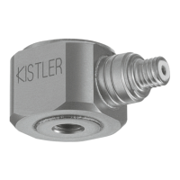
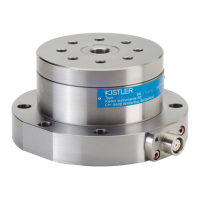
Explains the principles of piezoelectric measurement and sensor types.
Tips for using piezoelectric sensors, cables, and handling measurement ranges.
Describes the different measuring modes (DC (Long), Medium, Short).
Illustrates signal behavior in DC (Long) vs AC (Short, Medium, High-pass Filter) modes.
Guidance on the proper disposal of electronic equipment.
Explains how the Charge Meter operates and its key advantages.
Provides a detailed block diagram of the Charge Meter's architecture.
Details the functionality and components of the amplifier unit.
Explains the voltage input and digital signal processing within the amplifier.
Describes the functions of the control unit, keypad, LCD, and interfaces.
Details the power supply specifications and operation.
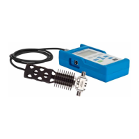
Illustrates a typical measurement setup including sensors, cables, and the instrument.
Explains the instrument's display, LEDs, buttons, and control knob.
Details the electrical connections on the back of the instrument.
Step-by-step guide for connecting the instrument and sensors.
Discusses input insulation, EMC, and ground loops for proper operation.
Details connections for remote control, voltage output, serial, and IEEE-488 interfaces.
Explains the instrument display layout and main menu options.
Describes how to navigate and select options within the instrument's menus.
How to change the instrument's display language.
Procedure for entering numerical values for settings like range and sensitivity.
Guide for performing direct force measurements with the instrument.
Details on starting, stopping, and evaluating measurements, including instantaneous and peak values.
How to set sensor sensitivity, units, and voltage output scaling.
Instructions for setting high-pass and low-pass filters and using the bar graph display.
Guide for performing indirect force measurements, e.g., for calibration.
Procedure for adjusting and aligning the shunt measuring chain.
Details on PC software, LabVIEW driver, and demo programs.
How to adjust the contrast of the liquid crystal display.
Procedure for locking and unlocking instrument settings to prevent accidental changes.
How to set and adjust the measuring range of the instrument.
Setting the measuring range in discrete steps.
Setting the measuring range to any desired value.
How to enable automatic adjustment of the measuring range.
How to set the sensor sensitivity and select units.
How to scale the voltage output range of the instrument.
How to assign functions to the [F] key.
How to control the measurement cycle and the measuring window.
Procedure for electronically setting the input stage to zero.
How to set and use the low-pass filter to attenuate interference.
How to set and use the high-pass filter for quasi-static measurements.
Explanation of the bar graph display and its scaling.
How to define the unit of measurement for displayed values.
Lists U.S. units for mechanical measurements.
Information on how the instantaneous value is updated.
How to perform and display signal evaluations like min, max, and mean.
How to record measurements and view statistical data.
How to restrict signal evaluation to a specific time window.
How to save and load instrument configuration settings.
How to activate demonstration mode for training purposes.
How to change the instrument's display language.
How to view instrument hardware options and software versions.
Explanation of warning and error messages displayed by the instrument.
Details on setting up and using the RS-232C serial interface.
Details on setting up and using the IEEE-488 interface.
Specifications for the charge input connector and its performance.
Specifications for the voltage and Piezotron input connectors.
Specifications for the voltage output connector and its performance.
Details on frequency response characteristics, including filters.
Specifications for the analog high-pass filter.
Specifications for digital low-pass filter functions.
Parameters for signal evaluation, including sample rates and pulse width.
Information on continuous data transfer to a PC.
Details on the remote control connector and input specifications.
Information on data communication interfaces.
Technical specifications for the RS-232C serial interface.
Technical specifications for the IEEE-488 interface.
Details on the power plug, voltage, fuses, and consumption.
Specifications for operating temperature, humidity, vibration, and shock.
Safety precautions related to maintenance and diagnosis.
Explains the causes of output signal drift in DC (Long) mode.
Detailed analysis of drift causes (Cause 1, 2, 3) and recommended actions.
Procedures for testing the instrument's functionality and calibration.
Information on Kistler's calibration services and accreditation.
Instructions for updating the instrument's firmware.
Step-by-step guide for replacing fuses F1 and F2.
Procedure for replacing the input operational amplifier.
Mathematical description of the charge amplifier's transfer function.
Mathematical description of the high-pass filter's characteristics.
Graphs showing gain and phase response of the charge amplifier.
Explanation of low-pass filter effects on frequency spectrum.
Examples of connections for controlling the instrument remotely.
Wiring diagrams for RS-232C null-modem and PC link cables.
Information about the LabVIEW driver for instrument control.
General configuration of the LabVIEW Virtual Instrument.
Lists requirements for operating the LabVIEW driver.
Lists functions not supported by the LabVIEW driver.
Using the LabVIEW VI for RS-232C measurements.
Using the LabVIEW VI for IEEE-488 measurements.
Detailed command list for RS-232C/IEEE-488 interfaces.
Details on command codes, parameters, and descriptions.
Command codes for local control and measuring range settings.
Describes methods for continuous data transfer.
Describes ASCII and Binary data transfer modes.
Settings for continuous data transfer, including sampling rates and filters.
Formal statement of the product's compliance with EU directives and standards.
| Brand | Kistler |
|---|---|
| Model | 5015A Series |
| Category | Measuring Instruments |
| Language | English |