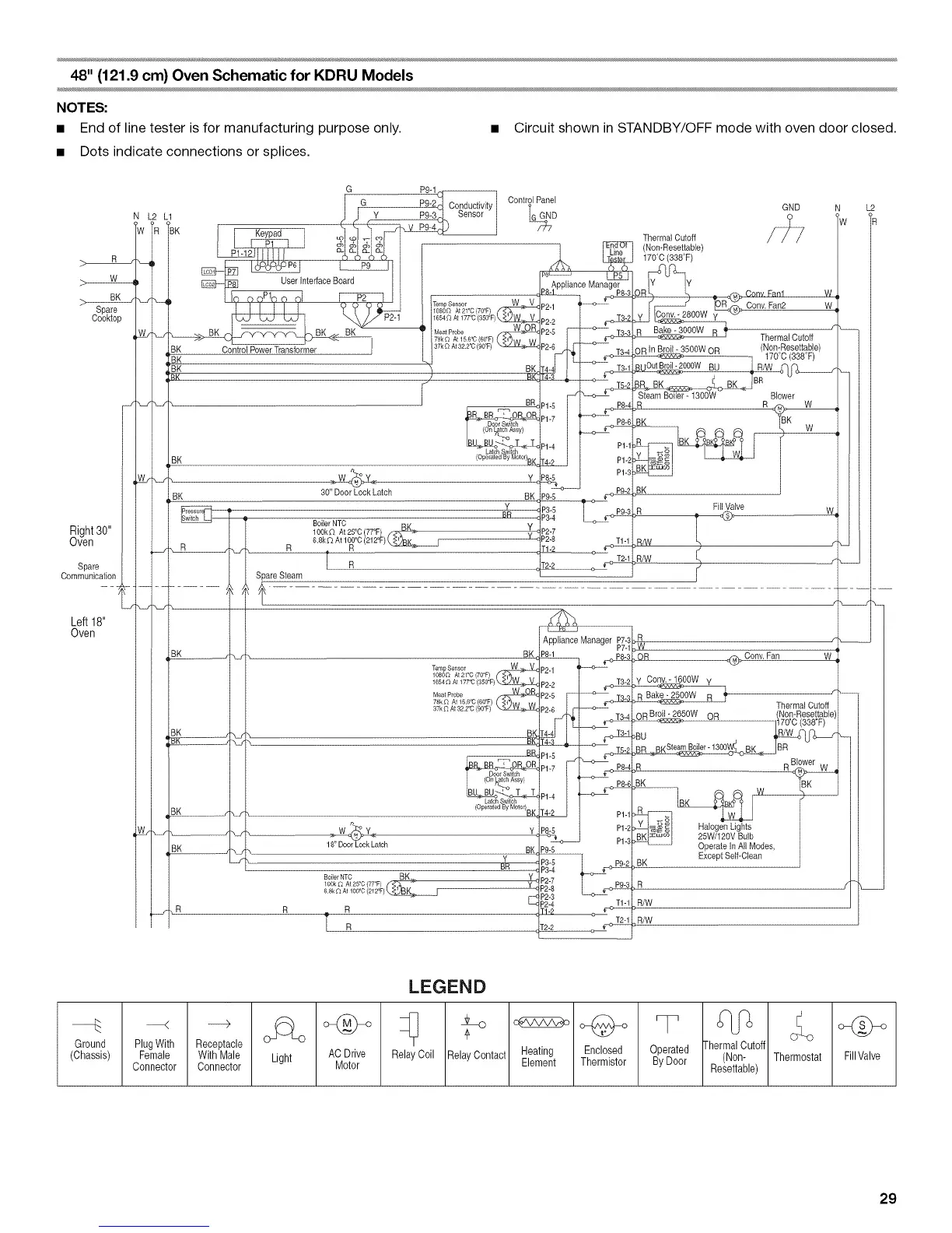
48" (121.9 cm) Oven Schematic for KDRU Models
NOTES:
• End of line tester is for manufacturing purpose only. • Circuit shown in STANDBY/OFF mode with oven door closed.
• Dots indicate connections or splices.
Right30"
Oven
Spare
Communication
G P9-1
[- G _ r_n,_,,_i_m, I Control Panel
N L2 L1 Jj Y P;_°_c_Jv'_Yl iGGND
'W >R <BK Keypad ,_I_ot f_o_
p o_ _ _ _.. Line
_ _ PL2_J
user'nterfaceBo=II I App,anc,Manager
P I I I I I I Y T T 1_}--_-4_ At21_OmYF}('¢_ ..... -' I
_ _ B.._BK_KK -- BK BK T / MeatP,obe _ P2-5 I I _^ T3-3
/J _-I 1_ _ I / /78k_ At156+C1601:)( _13tM IA/ I _
37k O At 32 2'0 (_1:) >_ P2-6 -o---
BK Control Power Transformer I [ / " P2-6_ [ T3-4
"BK L/ I ITI
I BK _ BK T4-4_ I_
"_z w ,,_ __ I BR P1-5 [ [ P8-4
nUl!b_,>!_o"4"-:oX-_Z Pt-4 I I Pt-t
BK 30" Door Lock Latch BK Pg-_
Jo _ B_-_
BoilerNTC pn P3-4 I_ _::>_
lOOk_ At25°C 77<I:) /-4_8K-_" Y P2-7
P2-8 T1-1
6.8kC_At 1_:_C212t:
T1-2
_J
{ _r',J
J
R
R
Spare Steam
Left 18"
Oven
BK c
Meat Probe
78k_ At 156% 601:)
37k £z At 322"C 901:
_W_
18" Door Lock Latch
R
TR
BP
BK
7_
(Operated By MotOr)B K
BK
Y
c
Appliance Manager P7-3
P7-1
P8-1
P_-I
P2-2 I
P2-5 __
P2-6 I
Bt-
r4-2 I I P1-1
I P1-2
---c----> P1-3
P9-5
B_-_ _ ,+_
P3-4
P2-3
_2-4 T1-1
r2-2
GND
Thermal Cutoff
(Non-Resettable)
170+C(338T)
,OR _ Cony Fan1 W
Conv, Fan2 W
y Conv-2800W
_OOOW B ]_ Thermal Cutoff r
OR In Broil- 3500W OR (N°n:Res2t!a. b!e)
_OOOW BU ; RIW _o_-
_eB
Steam Boiler- 1300W Blower
_R R _
BK
FillValve
R _
R!W t
R/W L)
[
OR _Conv. Fan
W
Conv.- 1600W y
Thermal Cutoff
(
OR Broil -2650W OR (Non-Resettable)
.... ]170°C (338°F)
,BU R/W_Z_-oF'Oqo_F
P.m _'Steam Boiler-1300W_ BK IBR
)R R Blower W
BK
Operate In AllModes,
BK Except Self-Clean
R/W
R/W
L2
PlugWith Receptacle
Female With Male
Connector Connector
LEGEND
_ RelayCoil melav_Contact _ °_
AC Drive _ H Enclosed
Motor Thermistor
Operated lhermal Cutoff
By Door / Re_N_tnable)
Thermostat
29
 Loading...