Tip Over Hazard
A child or adult can tip the range and be killed.
Connect anti-tip bracket to wail behind range.
Reconnect the anti-tip bracket, if the range is moved.
Failure to follow these instructions can result in death or serious burns to children and adults.
INSTALLATION REQUIREMENTS
Gather the required tools and parts before starting installation.
Read and follow the instructions provided with any tools listed
here.
Tools needed
• Tape measure • 1/4",3/8",%e" nut drivers
• #2 Phillips screwdriver • 3/W'carbide tip masonry bit
• %" x 41¼'' flat-blade • Marker or pencil
screwdriver
• Pipe-joint compound
• Level resistant to LP gas
• Drill • Noncorrosive leak-detection
solution
• Wrench or pliers
• Pipe wrench • Tubing cutter
• Adjustable wrench or For LP/Natural Gas
8/8"wrench Conversions
• 3/8"drive ratchet • Adjustable wrench
• 1/8"drill bit • 1/2"deep-well socket
• 1%6"combination wrench • 7 mm nut driver
• Masking tape
Parts supplied
Check that all parts are included.
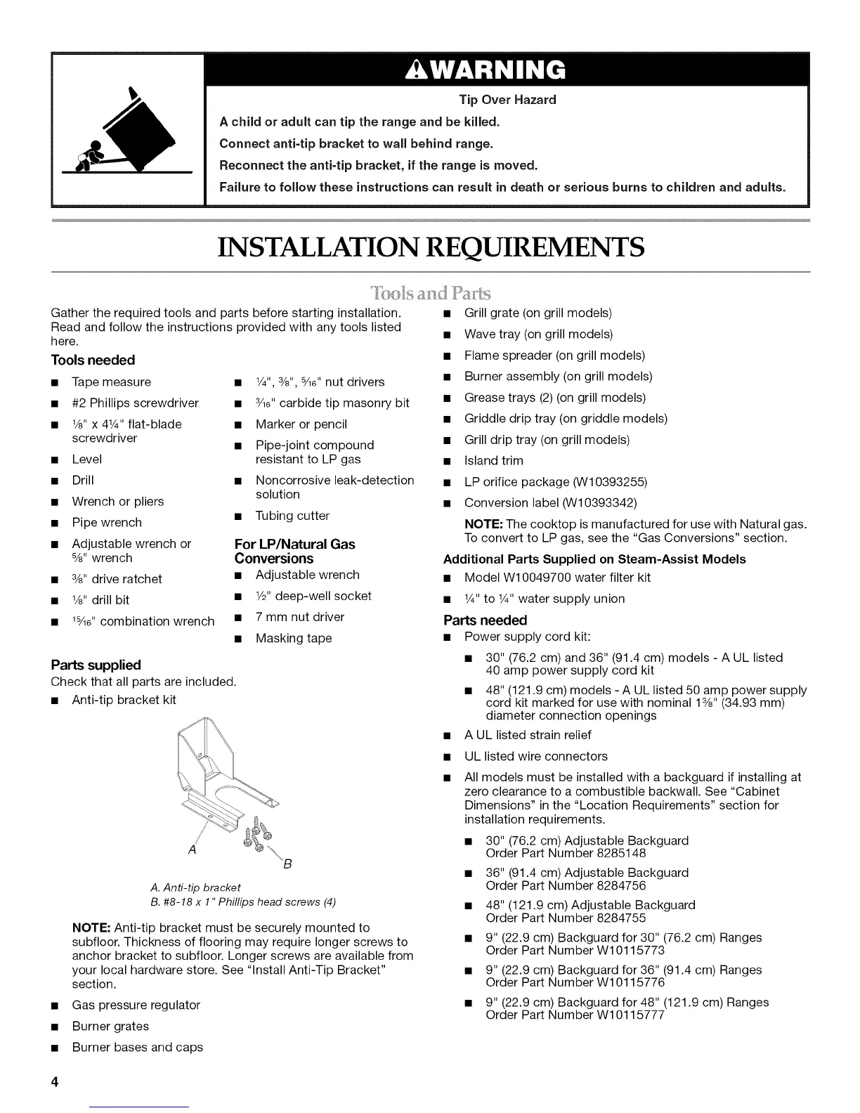
• Anti-tip bracket kit
• Grill grate (on grill models)
• Wave tray (on grill models)
• Flame spreader (on grill models)
• Burner assembly (on grill models)
• Grease trays (2) (on grill models)
• Griddle drip tray (on griddle models)
• Grill drip tray (on grill models)
• Island trim
• LP orifice package (W10393255)
• Conversion label (VV10393342)
NOTE: The cooktop is manufactured for use with Natural gas.
To convert to LP gas, see the "Gas Conversions" section.
Additional Parts Supplied on Steam-Assist Models
• Model W10049700 water filter kit
• 1¼.to 1¼.water supply union
Parts needed
• Power supply cord kit:
• 30" (76.2 cm) and 36" (91.4 cm) models - A UL listed
40 amp power supply cord kit
• 48" (121.9 cm) models - A UL listed 50 amp power supply
cord kit marked for use with nominal 13/8"(34.93 mm)
diameter connection openings
• A UL listed strain relief
• UL listed wire connectors
A. Anti-tip bracket
B. #8-18 x 111Phillips head screws (4)
NOTE: Anti-tip bracket must be securely mounted to
subfloor. Thickness of flooring may require longer screws to
anchor bracket to subfloor. Longer screws are available from
your local hardware store. See "Install Anti-Tip Bracket"
section.
• Burner grates
Gas pressure regulator
All models must be installed with a backguard if installing at
zero clearance to a combustible backwall. See "Cabinet
Dimensions" in the "Location Requirements" section for
installation requirements.
• 30" (76.2 cm) Adjustable Backguard
Order Part Number 8285148
• 36" (91.4 cm) Adjustable Backguard
Order Part Number 8284756
• 48" (121.9 cm) Adjustable Backguard
Order Part Number 8284755
• 9" (22.9 cm) Backguard for 30" (76.2 cm) Ranges
Order Part Number W10115773
• 9" (22.9 cm) Backguard for 36" (91.4 cm) Ranges
Order Part Number W10115776
• 9" (22.9 cm) Backguard for 48" (121.9 cm) Ranges
Order Part Number W10115777
• Burner bases and caps
 Loading...