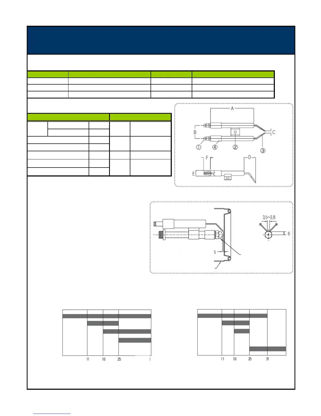
EasyManua.ls Logo

Kiturami TURBO-21 - Ignition Bar

Kiturami TURBO-21
36 pages
Print Icon
To Next Page IconTo Next Page
To Previous Page IconTo Previous Page
Loading...
4 - 5 IGNITION BAR
▶ SPECIFICATION
▶ Name and Dimension
60
70
26
3.5
24 3
11
14
▶ How to adjust the location of ignition rod
1. Ignition rod carries 16.5k voltage. Before adjusting,
plug off the power cord.
2. Don't adjust it at your discretion, it has been adjusted
minutely out of factory.
3. If necessary, adjust the ignition rod as shown Figure.
4. Epoxy material protects electrode rod and prevent
electrical short. Lots of soot may cause the inter
mittent ignition fault or ignition delay by electrical
discharges. Therefore, check the soot and epoxy damage.
▶ TIME CHART
◈ Normal combustion ◈ Abnormal combustion
C
2
Thermal Resistance
10
14
- 10
15
Ωcm
DIMENSION (mm)
Withstanding voltage
NAME
190 ℃
Epoxy
F
E
4
B
TURBO-21
18 KV/mm
Electrode rod
Connection hole
H
ardness
97 M
ITEM
5.3
VALUE
196 s
e
c
D
A
D
ielectric Constant
ITEM
VALUE
Insulation Resistance
Ignition rod
A
RC Resistance
1
TURBO-17
Ignition transformer
Connection nipple
ALARM
FAN
I/G Transformer
Ignition bar
Nozzle adapter
Nozzle
stabilizer
Electronic pump
Flame sensing
ALARM
FAN
I/G Transformer
Electronic pump
Flame sensing
sec sec
20페이지

Related product manuals