DocumentNo.:KE-4025-06 41/50
4.Applysomeliquidgasket(KITZstandard:ThreeBond1206E)tothecontactfacesofthehousing〈1〉,rod
guideA<136A>,rodguideB<136B>,springcase<100>,springcover<158>andcylinder<2>.
5.Aftercompletionofactuatorassembly,checkthevalveopeningandclosingpositionsandattachedposition
indicatorandmountthebracket〈93〉.
■PositionAdjustment
1. Adjust the valve opening and closing positions by adjusting the bolt <132> on the cylinder side and the
stopper<49>onthespringcoverside.
2.SeeChapter15ofthisoperationmanualfordetailsofadjustment.
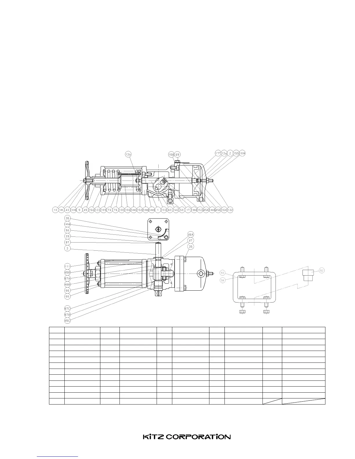
AssemblyDiagramofTypeBSW-0
No.
Parts No.
Parts No.
Parts No.
Parts No.
Parts
1 Housing 39 Screw 56 Tierod 98 Indicatorplate
140A Capscrew
2 Cylinder 43 Handlewasher 60 Key 100 Springcase 140B Capscrew
3 Shaft 45A Oring 67A Bearing 103 Pistonrod 140C Screw
9 Handwheel 45B Oring 67B Bearing 108 Guide 142 Scotchyoke
10 Capscrew
45C Oring 67C Bearing 109 Spring 145A Springwasher
13a Nut 45D Oring 76 Thrustbearing
111 Cautionplate 145B washer
13b Nut 47 Thrustbearing
78 Guidecap 123 Spindle 150 Springretainer
16A Plate 48A Snapring 89 Bolt 132 Adjustscrew 153 Roller
16B Washer 48B Snapring 92 Connector 133A Nut 155 Sealwasher
17 Pin 49 Stopper 93 Bracket 133B Nut 158 Springcover
35 Bolt 50 Breathingport 94 Bolt 136A Rodguide 177 Piston
36 Bolt 55 Nut 97 Indicator 136B Rodguide
Fig.28