Document No.:KE-4011-03 Page: 23/27
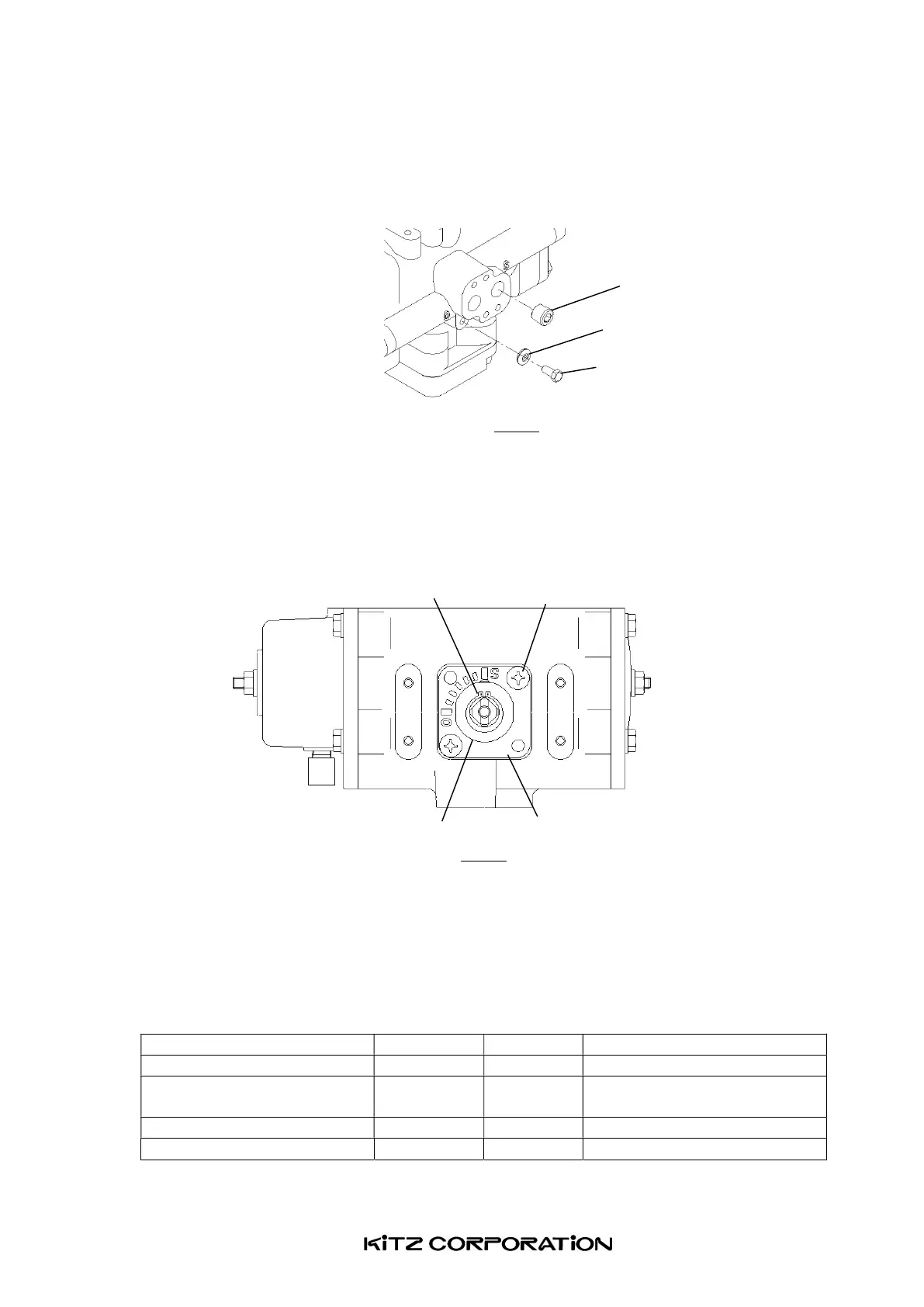
(12) Plug the leak detector hole with a seal washer and a hexagon headed bolt, to complete
reassembly of an actuator ( Fig.23 ).
Fig.23
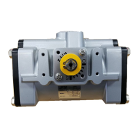
(13) Mount an indicator plate on top of the housing with two headed screws so that Mark [O]
may point (a) the left-hand of the housing for ball valves, or (b) the air inlet/outlet ports
for butterfly valves as shown in Fig.24. After checking correct mounting of the indicator
plate, assemble a position indicator through the shaft securely with a snap ring.
Fig.24
(14) Check trouble-free operation of reassembled actuators and mount them on valves.
(15) Insert Mizukiller on a breathing port of a spring case.
19.4 Bolt tightening torque
All bolts and screws shall be securely tightened with the torques recommended below:
Table.5 Recommended bolt tightening torques
Thread size
Threading torque values [N・m]
Piston / rack assembly Bolt <13A> M5 4~5
End cover /
spring cover mounting
Bolt <35> M6 10~12
Opening range adjuster bolt Nut <133> M6 3~5
Leak detector hole plugging Bolt <13B> M5 2~5
Plug <85>