38
Failure Display and Inspection
If an abnormality comes up, the induction hob will enter the protective state automatically and display cor-
responding protective codes:
Problem Possible Cause What to do
F3/F4 Temperature sensor of the induction coil
fail.
Please contact the supplier.
F9/FA Temperature sensor of the IGBT failure. Please contact the supplier.
E1/E2 Abnormal supply voltage Please inspect whether powersupply is
normal. Power on after the power supply
is normal.
E3 High temperature of the induction coil
temperature sensor.
Please contact the supplier.
E5 High temperature of the IGBT temperture
sensor.
Please restart after the induction hob cools
down.
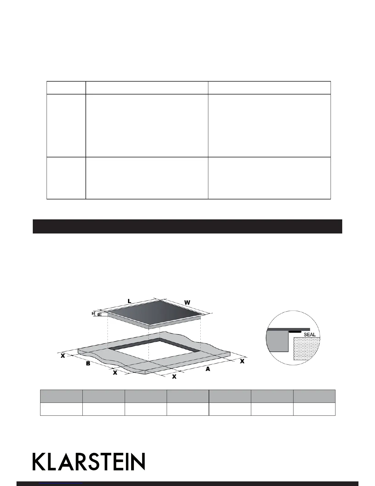
Installation
Selection of installation equipment
Cut out the work surface according to the sizes shown in the drawing.
For the purpose of installation and use, a minimum of 5 cm space shall be preserved around the hole.
Be sure the thickness of the work surface is at least 30mm. Please select heat-resistant work surface mate-
rial to avoid larger deformation caused by the heat radiation from the hotplate. As shown below.
L (mm) W (mm) H (mm) D (mm) A (mm) B (mm) X (mm)
590 520 55 58 560 490 50 mini