13
AC VOLTAGE
+
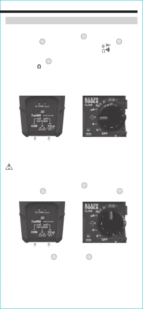
AC AMPERAGE FUNCTION
1. Insert RED test lead into VΩµA jack
5
, and BLACK test lead
into COM jack
4
, and rotate function selector switch
2
to the
V+A~ setting.
2. Press clamp trigger
10
to open clamp
3
and place around
current-carrying wire.
3. The main display will show AC Voltage and the secondary
display will show AC Amperage. Pressing the "SELECT" button
will reverse the displays; the main display will show AC
Amperage and the secondary display will show AC Voltage.
NOTE: The Hazardous Voltage Indicator will appear on the display
when the voltage is >25V AC or >60V DC.
OPERATING INSTRUCTIONS
RESISTANCE MEASUREMENTS
1. Insert RED test lead into VΩµA jack
5
, and BLACK test lead
into COM jack
4
, and rotate function selector switch
2
to the
Continuity/Resistance/Capacitance/Diode-Test setting.
NOTE: The meter defaults to Continuity testing in this mode. Press
the "SELECT" button
12
once to enter Resistance testing mode. The
Resistance icon will appear on the display.
2. Remove power from circuit.
3. Measure resistance by connecting test leads to circuit. The
meter will auto-range to display the measurement in the most
appropriate range.
NOTE: When in a Resistance setting and the test leads are open
(not connected across a resistor), or when a failed resistor is under
test, the display will indicate "OL". This is normal.
DO NOT attempt to measure resistance on a live circuit.
Red leadBlack lead
Red leadBlack lead