15
OPERATING INSTRUCTIONS
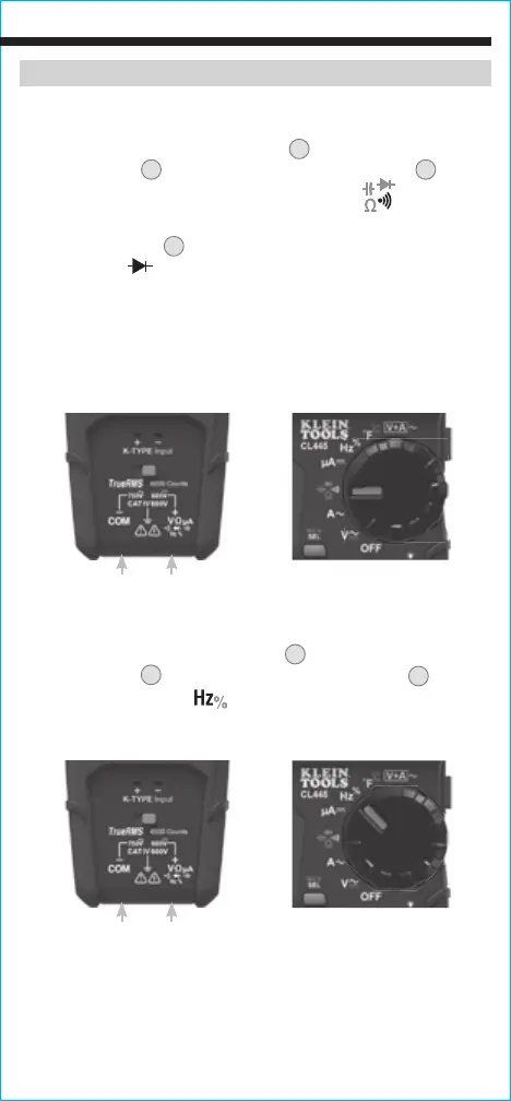
DIODE TEST
1. Insert RED test lead into VΩµA jack
5
, and BLACK test lead
into COM jack
4
, and rotate function selector switch
2
to the
Continuity/Resistance/Capacitance/Diode-Test
setting.
NOTE: The meter defaults to Continuity testing in this mode. Press
the "SELECT" button
12
three times to enter Diode testing mode.
The Diode icon
will appear on the display.
2. Touch test leads to diode. A reading of 200-800mV on display
indicates forward bias, "OL" indicates reverse bias. An open
device will show "OL" in both polarities. A shorted device will
show approximately 0mV.
FREQUENCY / DUTY-CYCLE
1. Insert RED test lead into VΩµA jack
5
and BLACK test lead
into COM jack
4
, and rotate function selector switch
2
to the
Frequency/Duty-Cycle
setting.
2. Measure by connecting test leads across the circuit.
Red leadBlack lead
Red leadBlack lead