8
ENGLISH
INCORRECT
CORRECT
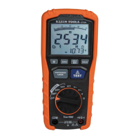
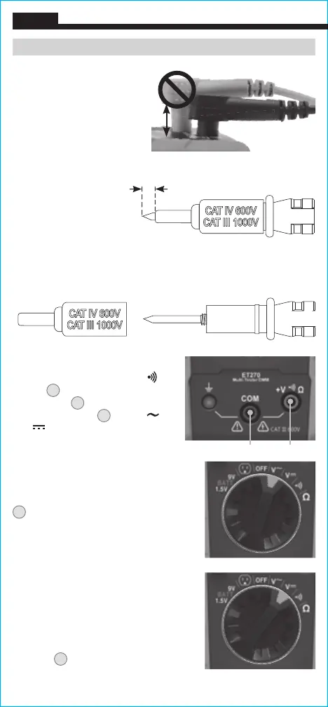
AC/DC VOLTAGE (LESS THAN 600V)
1. Insert RED test lead into
+
V Ω
jack
5
, and BLACK test lead into
COM jack
4
, and rotate Function
Selector Switch
2
to the V or
V setting.
2. Apply test leads to the circuit to
measure voltage. The tester will
auto-range to display the measurement
in the most appropriate range.
N
OTE: If the Negative Polarity Indicator
K
appears on the LCD, the test leads
are being applied to the circuit in reverse
polarity. Swap the position of the leads to
correct this.
NOTE: When in a voltage setting and the
test leads are open, readings of order mV
may appear on the display. This is noise
and is normal. By touching the test leads
together to close the circuit the tester will
measure zero volts.
NOTE: The Hazardous Voltage Warning
Indicator
N
will appear for voltages
above 25V.
Red leadBlack lead
-OR-
TESTING IN CAT III / CAT IV MEASUREMENT LOCATIONS
Ensure the test lead shield
is pressed firmly in place.
Failure to use the CAT III /
CAT IV shield increases
arc-flash risk.
5/32"
(4 mm)
CONNECTING TEST LEADS
Do not test if leads are
improperly seated. Results
could cause intermittent display
readings. To ensure proper
connection, firmly press leads
into the input jack completely.
OPERATING INSTRUCTIONS
TESTING IN CAT II MEASUREMENT LOCATIONS
CAT III / CAT IV shields may be removed for CAT II locations. This
will allow testing on recessed conductors such as standard wall
receptacles. Take care not to lose the shields.