9
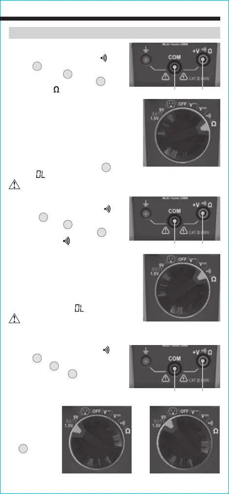
CONTINUITY
1. Insert RED test lead into
+
V
Ω jack
5
, and BLACK test lead
into COM jack
4
, and rotate
Function Selector Switch
2
to
the Continuity
setting.
2. Remove power from circuit.
3. Test for continuity by connecting
conductor or circuit with test leads.
If resistance is measured less than
10Ω, an audible signal will sound and
display will show a resistance value
indicating continuity. If circuit is open,
display will show "
".
RESISTANCE MEASUREMENTS
1. Insert RED test lead into V
Ω
jack
5
, and BLACK test lead
into COM jack
4
, and rotate
Function Selector Switch
2
to the
Resistance
setting.
2. Remove power from circuit.
3. Measure resistance by connecting test
leads to circuit. The tester will auto-
range to display the measurement in
the most appropriate range.
NOTE: When in a Resistance setting and
the test leads are open (not connected
across a resistor), or when a failed
resistor is under test, the LCD
1
will
indicate
" ".
This is normal.
DO NOT attempt to measure resistance on a live circuit.
Red leadBlack lead
Red leadBlack lead
OPERATING INSTRUCTIONS
DO NOT attempt to measure
continuity on a live circuit.
BATTERY TEST
1. Insert RED test lead into
+
V
Ω
jack
5
and BLACK test lead into
COM jack
4
, and rotate Function
Selector Switch
2
to the 1.5V or
9V BATT setting.
2. Connect BLACK lead to negative,
and RED lead to positive terminal
of battery.
3. The voltage
measured
will display
on the LCD
X
. Batteries
in good
condition
should be
within approx. 10% of rated voltage.
Red leadBlack lead
-OR-