ix
List of Figures
Figure 1-1: Splashproof TPU . . . . . . . . . . . . . . . . . . . . . . . . . . . . . . . . . . . . . . . . . . . . . 1-3
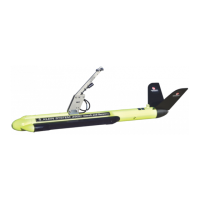
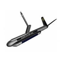
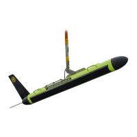
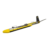
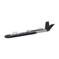
Figure 1-2: Towfish . . . . . . . . . . . . . . . . . . . . . . . . . . . . . . . . . . . . . . . . . . . . . . . . . . . . . 1-4
Figure 1-3: Towfish Block Diagram . . . . . . . . . . . . . . . . . . . . . . . . . . . . . . . . . . . . . . . . 1-7
Figure 1-4: Towfish Connector—at Towfish . . . . . . . . . . . . . . . . . . . . . . . . . . . . . . . . . . 1-8
Figure 1-5: TPU Block Diagram . . . . . . . . . . . . . . . . . . . . . . . . . . . . . . . . . . . . . . . . . . . 1-9
Figure 5-1: Splashproof TPU . . . . . . . . . . . . . . . . . . . . . . . . . . . . . . . . . . . . . . . . . . . . . 5-1
Figure 5-2: Splashproof TPU Vent Closed . . . . . . . . . . . . . . . . . . . . . . . . . . . . . . . . . . . 5-2
Figure 5-3: Splashproof TPU Vent Open . . . . . . . . . . . . . . . . . . . . . . . . . . . . . . . . . . . . 5-2
Figure 5-4: Splashproof TPU Connector Panel . . . . . . . . . . . . . . . . . . . . . . . . . . . . . . . 5-4
Figure 5-5: Inside the Cover of the Splashproof TPU Case . . . . . . . . . . . . . . . . . . . . . . 5-4
Figure 5-6: Front Panel of VME Chassis inside Splashproof TPU . . . . . . . . . . . . . . . . 5-6
Figure 5-7: VME Backplane and Power Supply Connections inside
Splashproof TPU . . . . . . . . . . . . . . . . . . . . . . . . . . . . . . . . . . . . . . . . . . . . . 5-7
Figure A-1: Correct Methods to Unreel Tow Cable . . . . . . . . . . . . . . . . . . . . . . . . . . . . A-1
Figure A-2: Spooling Real to Drum . . . . . . . . . . . . . . . . . . . . . . . . . . . . . . . . . . . . . . . . . A-2
Figure A-3: Cable Loop and Kink . . . . . . . . . . . . . . . . . . . . . . . . . . . . . . . . . . . . . . . . . . A-3
Figure A-4: Damaged Cable . . . . . . . . . . . . . . . . . . . . . . . . . . . . . . . . . . . . . . . . . . . . . . A-3
Figure C-1: Basic System Setup Diagram . . . . . . . . . . . . . . . . . . . . . . . . . . . . . . . . . . . . C-2
Figure C-2: System Setup Diagram with Acoustic Positioning System . . . . . . . . . . . . . . C-3
Figure C-3: Sample Plot of Tow Cable Characteristics . . . . . . . . . . . . . . . . . . . . . . . . C-29
Figure C-4: Setup for Measuring Tow Cable Characteristics using a
Function Generator, Terminator and Oscilloscope . . . . . . . . . . . . . . . . . . C-29
 Loading...