BAC-9000 Series Controller Installation Guide 3 921-019-01F
14
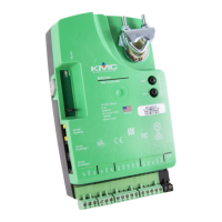
NOTE: The Ethernet patch cable should be a
maximum of 150 feet (45 meters).
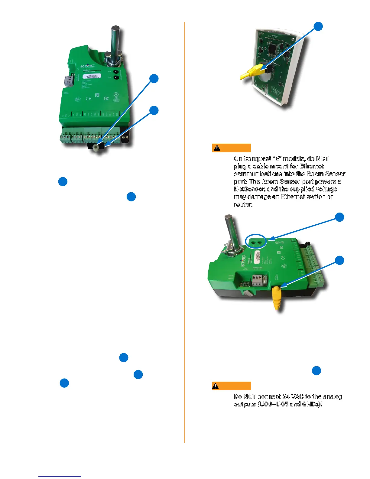
CAUTION
On Conquest “E” models, do NOT
plug a cable meant for Ethernet
communications into the Room Sensor
port! The Room Sensor port powers a
NetSensor, and the supplied voltage
may damage an Ethernet switch or
router.
15
16
NOTE: Auxiliary VAV equipment such as fans,
heaters, reheat valves, and discharge
air temperature sensors can be
connected to the controller.
2. Connect auxiliary VAV equipment to the input
and output green terminal blocks
17
.
CAUTION
Do NOT connect 24 VAC to the analog
outputs (UO3–UO5 and GNDs)!
NOTE: Use 24 VAC (only) with triac outputs
(BO6–BO9 with SC).
NOTE: Wire sizes 12–24 AWG can be clamped
in each terminal.
12
13
7. Attach the controller to the VAV box with a
#8 sheet metal screw through the mounting
bushing
12
.
8. Evenly tighten the V-clamp nuts
11
on the
drive hub to 30–35 in-lb.
CONNECT SENSORS AND EQUIPMENT
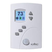
NOTE: A digital STE-9000 Series NetSensor
can be used for conguring the
controller (see Congure/Program
the Controller on page 7). After the
controller has been congured, an
STE-6010, STE-6014, or STE-6017
analog sensor can be connected to the
controller in place of the NetSensor.
See the relevant installation guide for
additional details.
NOTE: See Sample (BAC-9001) Wiring on
page 8 for more information.
1. Plug an Ethernet patch cable
14
connected
to an STE-9xxx or STE-6010/6014/6017
sensor into the controller’s (yellow
22
) ROOM
SENSOR
15
port.