BAC-9000 Series Controller Installation Guide 8 921-019-01F
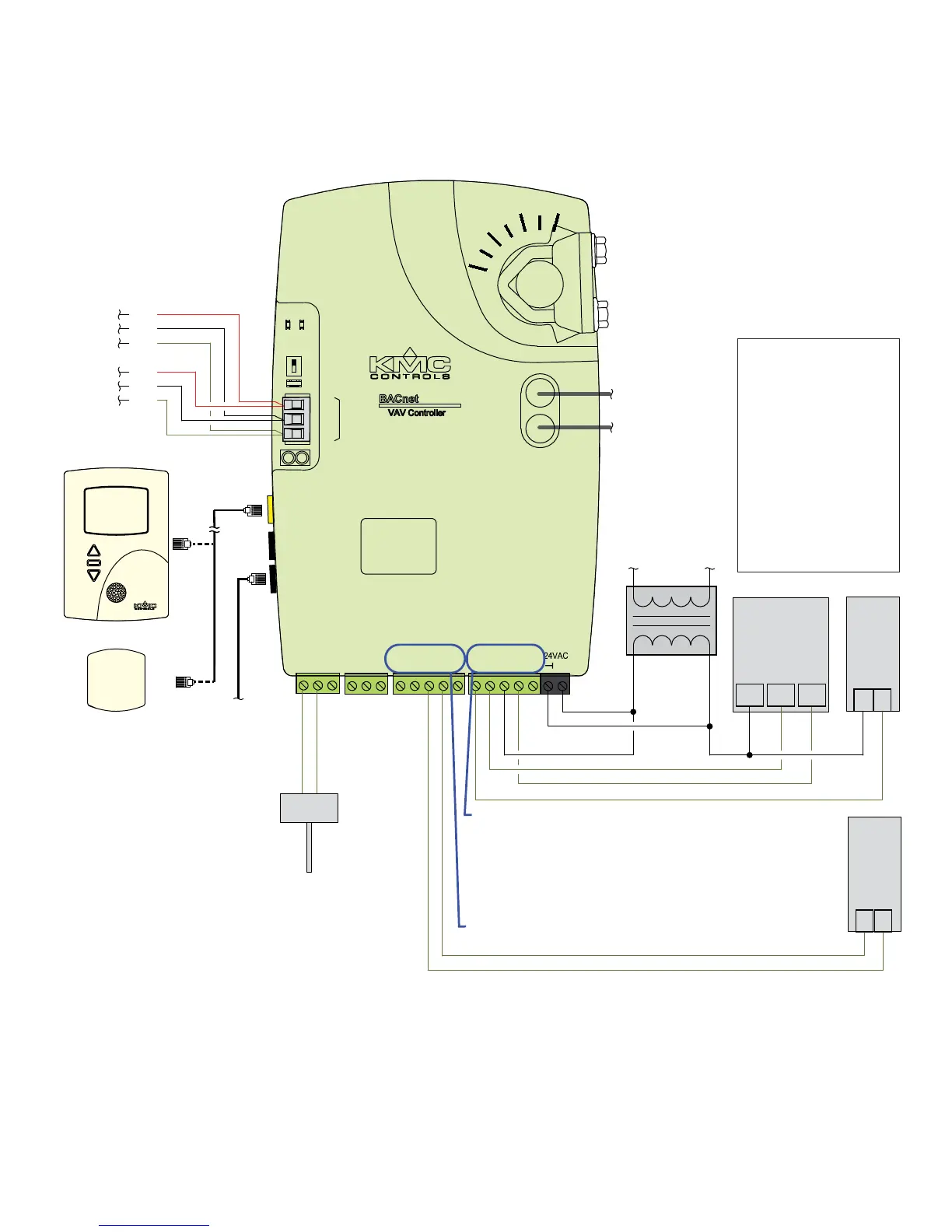
SAMPLE (BAC-9001) WIRING
DAT
10K Ohm
Type 3
Thermistor
Ethernet
To
BLK
SHLD
RED
Controller
Next
To
Controller
Previous
From
BLK
RED
SHLD
(Optional)
STE-1405
NOTE: Connect the STE-9xxx (or
STE-6010/6014/6017 with
no ventilation control) sensor
to the Room Sensor port
using a max. of 150 feet
of Ethernet patch cable.
CAUTION: Do NOT connect 24 VAC to the
analog outputs (UO3–UO5 and GNDs)!
NOTE: For MS/TP models, turn the
End Of Line switch ON at both
physical ends of the MS/TP
network. Connect the cable
shield to earth ground at only
one point.
NOTE: For Ethernet models, connect the
controller to the network with a
standard Ethernet patch cord.
NOTE: Analog inputs accept 1K or 10K
sensors, 0–12 VDC, or 4–20 mA.
NOTE: For more wiring examples, see the
wiring diagrams that are part of the
application library in KMC Connect,
Converge, or TotalControl.
STE-9521
STE-6010-10
(Single Duct VAV, Series Fan Powered with Floating Reheat and Vent Control)
L
H
1/4" (6.35) FR tubing
to flow sensor
~
COM
24 VAC
(Only)
~
Phase
Neutral
–
Fan
Start
Fan
Speed
+
–
OPEN CLOSECOM
Floating
Reheat
UI3
RDY
COM
GND
UI4
PRESSURE SENSOR
HIGH
LOW
-A
+B
S
BACnet MS/TP
EOL
10/100
ETHERNET
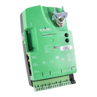
BAC-9001/9001CE Controller
~
H N
Line
Voltage
CONNECTIONS (SAMPLE)
UI3 = DAT SENSOR
INPUTS
OUTPUTS (Binary/Triac)
OUTPUTS (Universal/Analog)
ROOM SENSOR
NETWORK
POWER
MS/TP OR ETHERNET
UO4 = FAN SPEED
BO6 = FAN ENABLE
BO7 = OPEN VALVE
BO8 = CLOSE VALVE
UI5
GND
UI6
UO3
GND
UO4
GND
UO5
ROOM
SENSOR
BO6
BO7
SC
BO8
BO9
OFFON
NOTE: Use 24 VAC (only) on triac outputs
(BO6–BO9 with SC)!