BAC-9300 Series Controller Installation Guide 7 925-019-02G
GND
UI3
UI5
UI4
UI6
GND
UI7
UI8
GND
+B
-A
MS/TP
S
10/100
ETHERNET
ON
OFF
EOL
PRESSURE
SENSOR
HIGH LOW
DISCHARGE AIR TEMP
10KΩ, TYPE 3 Thermistor
BLK
SHLD
RED
Controller
Next
To
Ethernet
To
Controller
Previous
From
BLK
RED
SHLD
(Optional)
STE-1405
NOTE: Use 24 VAC (only) on triac
outputs (BO1–BO6 with SCs)!
NOTE: See the KMC Conquest Controller
Application Guide for information
about switched commons (SC),
using VDC power, and other issues.
NOTE: Connect the STE-9xxx (or
STE-6010/6014/6017 with
no ventilation control) sensor
to the Room Sensor port
using a max. of 150 feet
of Ethernet patch cable.
CAUTION: Do NOT connect 24 VAC
to the analog outputs
(UO7–UO10 and GNDs)!
NOTE: For MS/TP models, turn the End Of
Line switch ON at both physical ends
of the MS/TP network. Connect the
cable shield to earth ground at only
one point.
NOTE: For Ethernet models, connect the
controller to the network with a
standard Ethernet patch cord.
NOTE: Analog inputs accept 1K or 10K
sensors, 0–12 VDC, or 4–20 mA.
NOTE: For more wiring examples, see the
wiring diagrams that are part of the
application library in KMC Connect,
Converge, or TotalControl. Early
models shown in the drawings had
different terminal locations. Follow
the terminal labels (not location).
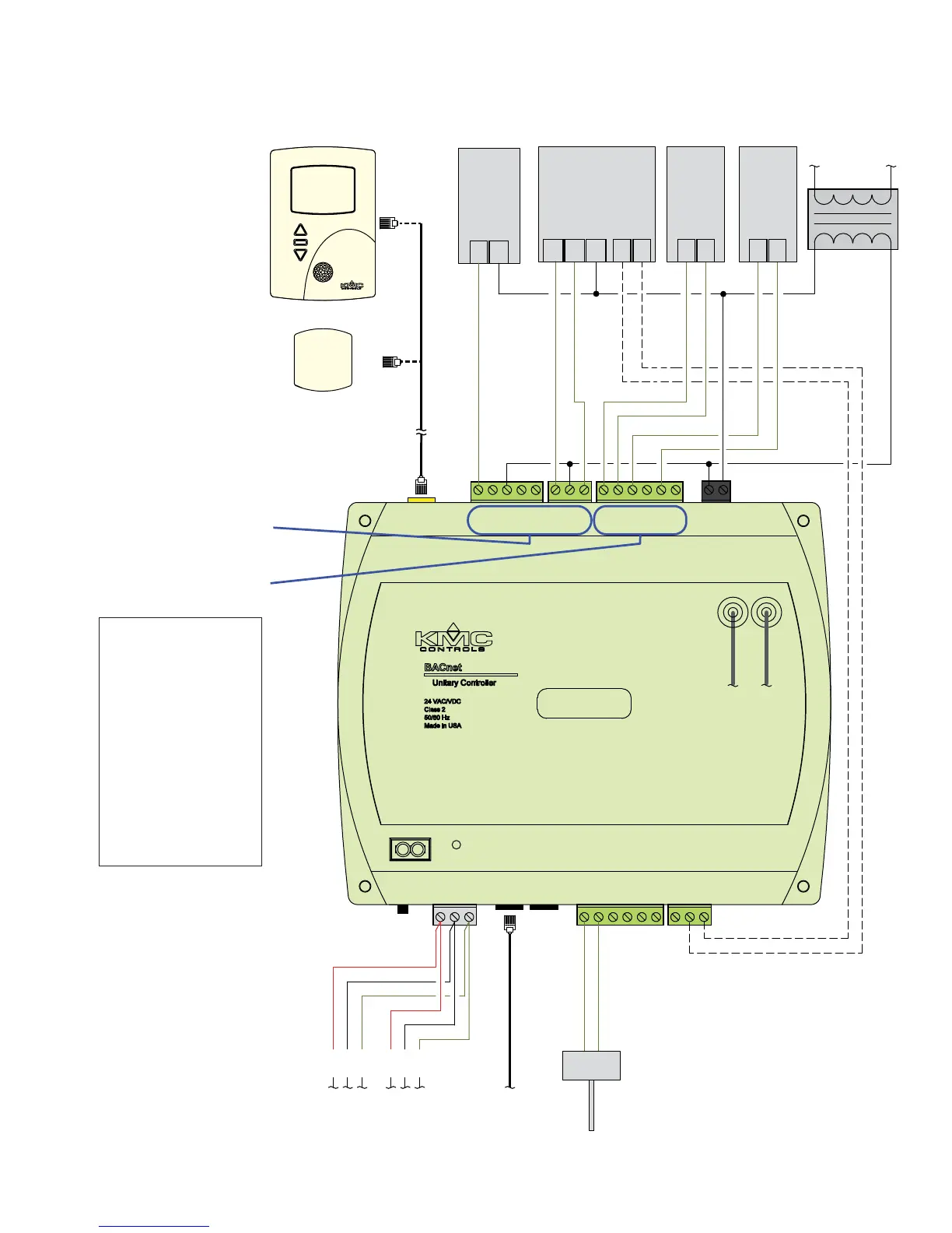
STE-9521
STE-6010-10
(Single Duct VAV, Series Fan Powered with Modulating Reheat and Vent Control)
(From Optional MEP-4x13 10K
Ohm Feedback Potentiometer)
BAC-9311 Controller
L
H
1/4" (6.35) FR tubing
to flow sensor
CONNECTIONS (SAMPLE)
UI3 = DAT SENSOR
INPUTS
OUTPUTS (Binary/Triac)
OUTPUTS (Universal/Analog)
UI8 = PRI POSITION
ROOM SENSOR
BO1 = FAN ENABLE
BO5 = PRI DAMPER CW
BO6 = PRI DAMPER CCW
UO7 = MOD REHEAT
UO8 = FAN SPEED
NETWORK
POWER
MS/TP OR ETHERNET
24 VAC/VDC
SC
BO6
BO5
ROOM
SENSOR
HN
Line
Voltage
24 VAC
Fan
Start
~
~
Primary
Damper
Actuator
P2CCW COM
COM
PhaseNeutral
CW P1
MEP-4001/
MEP-4013
~
–
–
–
SC
BO3
BO4
BO1
BO2
UO7
UO8
UO9
GND
UO10
GND
+
–
–
Fan
Speed
+
Mod
Reheat
SAMPLE (BAC-9311) WIRING
 Loading...