BAC-120063CW-ZEC FlexStat 5 Installation and Configuration Guide, Rev. G
Connections and Wiring
Wiring Considerations
• Because of the many connections (power,
network, inputs, outputs, and their respective
grounds or switched commons), be sure wiring
is well planned before installation of conduit!
• Make sure that conduit for all wiring has ad-
equate diameter for all necessary wiring. Using
1-inch conduit and junction boxes is recommend-
ed! Use external junction boxes above the ceiling
or in another convenient location as needed
to make connections that run to the FlexStat’s
junction box.
• To prevent excessive voltage drop, use a conduc-
tor size that is adequate for the wiring length!
Allow plenty of “cushion” to allow for tran-
sient peaks during startup.
• Using multiple conductor wires for all relevant
inputs and outputs is recommended. Grounds
for all the inputs can be combined on one wire.
CAUTION
To avoid damage from ground loops and other
communication issues in networked FlexStats,
correct phasing on MS/TP network and power
connections on ALL the networked controllers is
critically important.
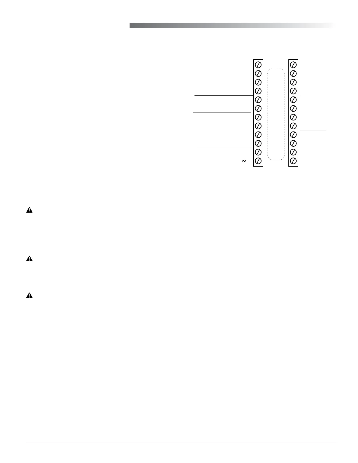
Illustration 5—Terminals and Connections
CAUTION
Relays are for Class-2 voltages (24 VAC) only. Do not
connect line voltage to the relays!
IN9
IN8
GND
IN7
+B
–A
IN4
IN3
GND
IN2
Common/–/C
Phase/ /R
Analog 9
GND 7–9
Analog 8
Analog 7
Relay 6
SC 4–6
Relay 5
Relay 4
Relay 3
SC 1–3
Relay 2
Relay 1
Outputs
(Wiring Cutout in Backplate)
MS/TP
Network
Inputs
24 VAC
(Wiring is
dependent on
application)
Inputs
NOTE: IN1 and IN5–6 are
reserved for internal sensors
NOTE: SC = Switched
(relay) Common
Output Connections
Connect the device under control between the desired
output terminal and the related SC (Switched Com-
mon for relays) or GND (Ground for analog outputs)
terminal. (See Illustration 5).
Optional connections (for rmware R2.0.0.4 and later)
are:
• A static pressure setpoint signal to a CSP-4702
pressure controller used with the system for
pressure bypass control on AO7. (Earlier rmware
had it on AO9 instead.) The static pressure feed-
back signal is on AI9. The setpoint value can be
changed in the Setpoints menu.
• Outside air damper (economizer) on AO9 with
the Additional Setup menu options of None,
Modulating, Disable/Enable. Connect to AO9 for
modulating or (on RTU only) BO6 for enable/
disable.
• A modulating valve on a hot or cold water coil on
AO8. This can provide primary or supplemental
modulating heating or cooling to the staged
heating or cooling. The Additional Setup menu
options for actuator device type are 0–10, 10–0,
2–10, or 10–2 VDC.
CAUTION
Do not mistakenly connect 24 VAC to an analog
output ground. This is not the same as a relay’s
switched common. See the backplate’s terminal
label for the correct terminal.

 Loading...