MEP-4xxx Direct-Coupled Actuators (40 to 90 in-lb.) 13 Applications Guide, AN0513A Rev. J
Index
Symbols
0-5/0-10 vs. 1-5/2-10 VDC Feedback: 10
0-10 vs. 2-10 VDC Inputs: 10
A
Accessories: 5
Applications: 4
Auto-Mapping: 10
Auxiliary Switch: 9, 12
B
Brackets, Non-Rotation: 7
C
Cable: 6
Conduit Fitting: 6
Configuration: 10
Cooling: 4
Cord Grip: 6
Crank Arm Kit: 5
CTE-5202: 4, 7
D
Damper Torque: 4
Direction: 9, 10, 11, 12
E
Enclosure Kit: 6
F
Fail-Safe: 9, 13
Feedback: 9, 10
H
HCO-1151: 6
Heating: 4
HLO-4001: 5
HMO-4001: 7
HMO-4002: 7
HMO-4004: 7
HMO-4521: 6
HPO-4001: 6
HPO-4051: 6
HPO-5073: 8
HPO-5074: 8
I
Important Notices: 3
Inputs: 10
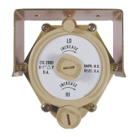
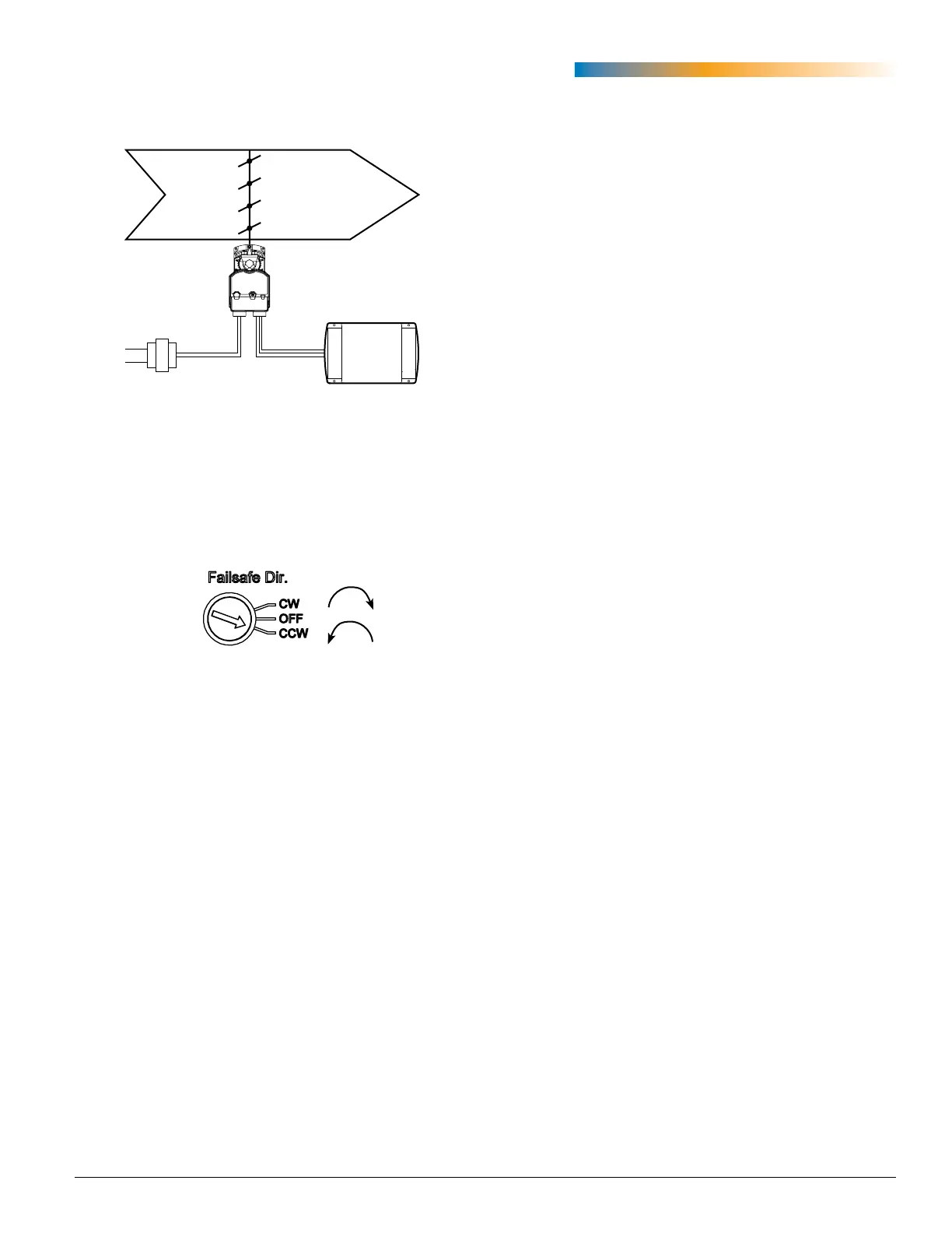
Fail-Safe Direction Switch Dial
Fail-Safe Direction (MEP-42/45/49xx)
NOTE: After initial connection or reconnection
to power on MEP-42x2/45x2/49x2
proportional models, proper fail-safe
operation might be delayed up to 30
seconds (until the capacitors are fully
charged).
OAD
24 VAC
Fail-Safe
MEP-4xxx
BAS
All fail-safe MEP-42xx/45xx/49xx models oer
selectable clockwise or counterclockwise direction.
(Proportional and tri-state models also oer the op-
tion to turn the fail-safe o—usually temporarily for
test purposes.) Using a small, at-bade screwdriver,
adjust the switch dial to the desired CW/OFF/CCW
option.