Section 9
High Pressure Water System
20412997
8-2012/Rev 12
9-3
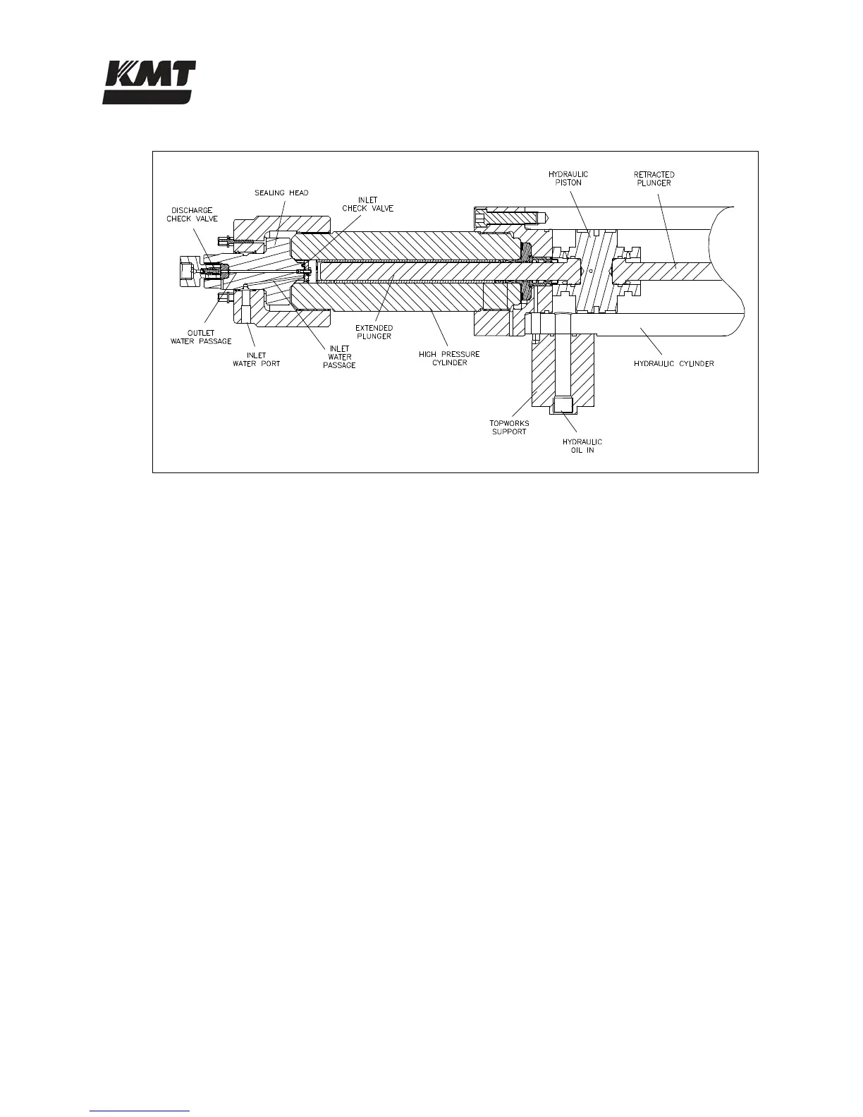
Figure 9-3: High Pressure Cylinder
Low pressure water is routed through the inlet water ports to the inlet passages in the sealing
heads. When the plunger retracts, the inlet check valve opens to allow water to fill the high
pressure cylinder. When the plunger extends to create high pressure water, the inlet valve closes
to seal the inlet passage and the discharge check valve opens to allow the high pressure water to
exit the cylinder. As the plunger retracts, the discharge check valve closes.
The intensifier is a reciprocating pump. As the piston and plungers move from one side to the
other, high pressure water exits one side of the intensifier as low pressure water fills the opposite
side.
The high pressure water is then routed to the attenuator. The attenuator acts as a shock absorber
to dampen pressure fluctuations and ensure a steady and consistent supply of water. From the
attenuator, the high pressure water exits to the cutting head.
The safety dump valve releases the stored pressure in the intensifier and high pressure delivery
lines. The high pressure dump valve assembly includes a normally open high pressure water
valve and an electrically controlled air valve.
The normally open pneumatic dump valve is held closed by air pressure. When the air supply is
interrupted and exhausted from an emergency stop, the valve opens and allows water to flow
through the valve. Pressure is released in the intensifier and the high pressure water stream exits
through the drain.
Redundant Intensifiers
If the machine is equipped with redundant intensifiers, the cutting water supply lines are
manually connected to the inlet water ports on the active intensifier. Manual hydraulic valves are
opened or closed to direct the hydraulic flow to the active intensifier. Manual high pressure water
valves are also opened or closed to direct the high pressure water flow from the active intensifier.
Control is switched from one intensifier to the other from the Run Screen on the control panel.
 Loading...